Previous
Entry Top Next
Entry
10/26/2004 - Interfacing the Motors, Sensors & Soil
Sampler to the OOPic II
Overview
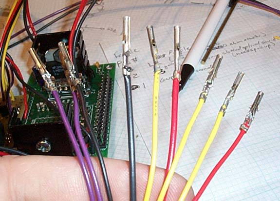
Photo showing the completed interface for the Leg Section

The
nine wires coming from each Motor as well as the Soil Sampler
must be interfaced to the OOPics.
This
involves two circuit boards, one purchased off the shelf and another
which I designed and had produced for me.
The
first is the Magnevation
Dual PMW Driver Board which I purchased. This printed
circuit board (PCB) allows the OOPic to control two DC motors.
It has inputs for ground and the motor voltage (24vDC in
my case) and outputs two wires for each motor. It is made
to work with the OOPic and the two are connected together via
their 40 pin connectors using a short ribbon cable.
Our
other 7 wires (S1, S2, S3, L1, L2, +5vDC, GND) feed out of a custom
designed PCB which I created using the service provided by www.ExpressPCB.com
This Encoder Interface Board (EIB) provides a spot for the resistors
and transistors needed to allow the OOPic to power (L1, L2, GND,
+5vDC) and read the Encoder outputs (S1, S2) and the optical switch
output (S3).
Here's
a photo of my Encoder Interface Board with components:
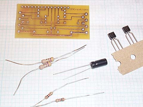
Here
are the EIB's circuit diagram and the board layout files. Note
that you'll need the free ExpressPCB
software to open these!
EIB
Circuit Diagram
EIB Board
Layout
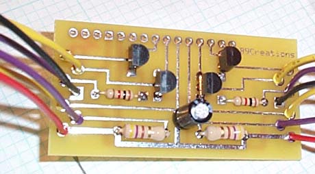
Here's
a shot of the EIB after build up:
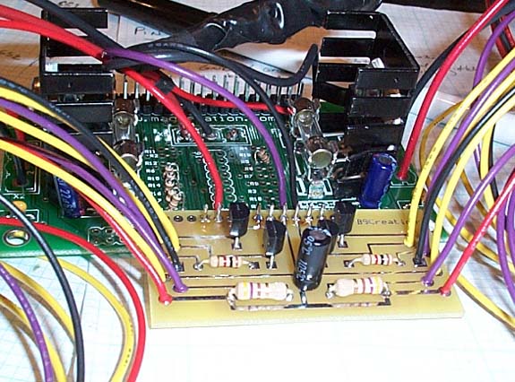
And
Here it is attached to the Magnevation Dual PWM board.
Molex
terminals crimped and soldered.
Optical
Switches
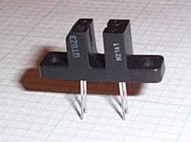
I'm
using a H21A1/2/3 Slotted Optical switch. This
device has four pins (1-4). Pins 2&4 go to Ground, Pin
1 connects to L1 & Pin 3 is the output which connects to S3.
Here's the data sheet
for this switch (pdf). These can be purchased from
DigiKey. (DigiKey part #
H21A1-ND, $1.08 each)
Between
the EIB and the Magnevation Dual PWM we have completely interfaced
both of the 9-pin motor connectors (both the Hip Actuator motor
and the Torso Rotation motor).
Soil
Sampler Control
That
leaves the Soil Sampler interface as the last responsibility of
the leg section OOPic.
I
had planned to use relays but decided it would be best if I could
come up with a solid state circuit that the OOPic could use to
control the Soil Sampler.
I also wanted to be able to stop the Soil Sampler in mid-motion
when the Power Pack is pulled. So I bring both the
SS's ground supply wire and it's trigger wire up to the OOPic
using a two wire cable. Black(SS1) is the SS's ground
line (cut this and everything stops, ie Power Pack pulled). Purple(SS2)
is the SS's Trigger line (hold this to ground for about three
seconds to start the cycle).
I
didn't make a PCB for this. Instead I soldered everything together
in-line and used wire shrink tube to protect it. Basically
there are two circuits, SS1 & SS2, each of which can connect
it's output line to ground under OOPic Control. The
OOPic will control the Soil Sampler by grounding SS1 (cycle power)
for 20 seconds (long enough to cycle) and SS2 (trigger ground)
for about three seconds. If the power pack is pulled then
SS1 can be opened and the Soil Sampler will stop moving until
SS2 is closed again (Power pack plugged back in).
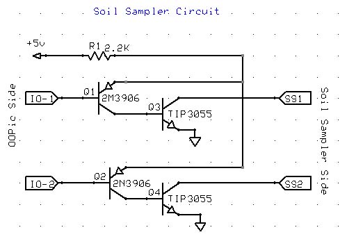
I
used some transistors from Radio Shack to construct the solid
state relays.
Here's the
circuit I used:
(Click
here to Download the ExpressPCB Circuit File)
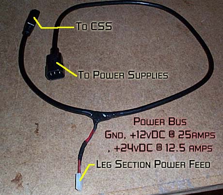
Power
Bus and OOPic Power connections
I'm
using 16 gauge AC power cords to bus DC power through the Robot.
They are readily available, flexible, and can be purchased
with connectors on each end.
The
ones I am using are three wire conductors. I'm using Green
as Ground, Blue as 12vDC and Brown as 24vDC. A patch cord
with a sliced in feed for the leg section circuits is used in
the leg section:
OOPic
I/O Line Usage
Every
sensor(input) and every output from the OOPic needs a dedicated
I/O line. Here's a list of the I/O lines used and their
connection.
I/O
Line 1: SS1 - Active Low Output. Connects the Soil
Sampler's Ground line.
I/O Line 2: SS2 - Active Low Output. Triggers the Soil Sampler
cycle when held low for three seconds.
I/O
Lines 18, 24 & 26 - PWM outputs for motor 1 (Hip actuator).
I/O
Lines 17, 25 & 27 - PWM outputs for motor 2 (Torso Rotation).
I/O
Lines 15 & 14- Motor 1 (hip) Encoder inputs (S1, S2).
I/O Lines 13 Motor 1 (hip) Optical switch input (S3)
I/O
Lines 10 & 11- Motor 2 (torso) Encoder inputs (S1, S2).
I/O Lines 12 Motor 2 (torso) Optical switch input (S3)
Previous
Entry Top Next
Entry


 Mike
J. ( B9-0002 )
Mike
J. ( B9-0002 )