Previous
Entry Top Next
Entry
10/06/2004 - More Homemade Motor Shaft Encoders
Wire
Harness
The
plan is to have each motor exactly alike to make using them
easier. Each motor will have a 9-pin .062 Molex connector. 6
of the pins will go directly to the motor. ( 2 wires for motor
power, 4 wires to the encoder ) The other 3 wires
go to a 3 pin connector. That connector will allow the
"neutral position" optical switch output to be fed
to the OOPic through the same bundle. Here's the
Pin out of the two connecters:
9
Pin male Motor Connector
1 - L1 - Ground thru 1.0K ohm resistor (Green encoder wire)
2 - S1 - Encoder sensor 1 (Blue encoder wire)
3 - S2 - Encoder sensor 2 (Orange encoder wire)
4 - +5vDC - (White encoder wire)
5 - Motor Lead 1 (Green Motor wire)
6 - Motor Lead 2 (Red Motor wire)
7 - Pin 1 of 3-Pin Connector - Ground (Black)
8 - Pin 2 of 3-Pin Connector - S3 (Yellow)
9 - Pin 3 of 3-Pin Connector - L2 (Purple)
3
Pin female Optical Switch Connector
1 - Ground (Black wire)
2 - S3 - Optical switch sensor (Yellow wire)
3 - L2 - +5vDC thru 95-120 ohm resistor (Purple wire)
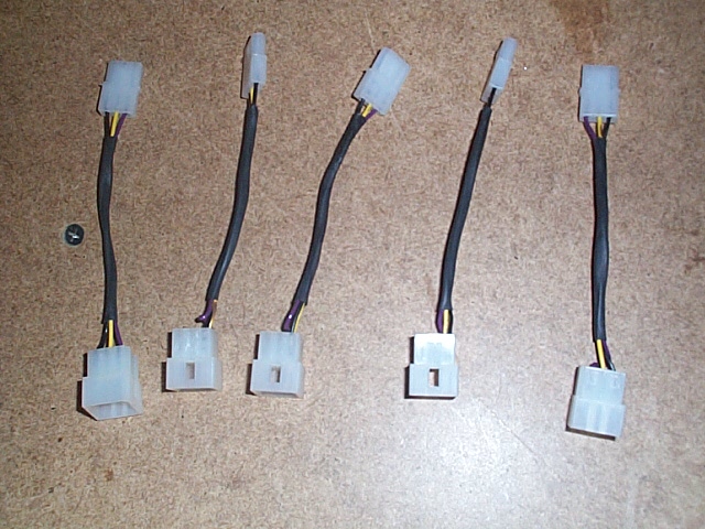
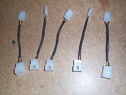
Here's
a shot of the 9 pin connector with the 3-Pin connector off shoot
already assembled. I used 4" wire lengths. Note
the use of shrink tubing to keep things neat.
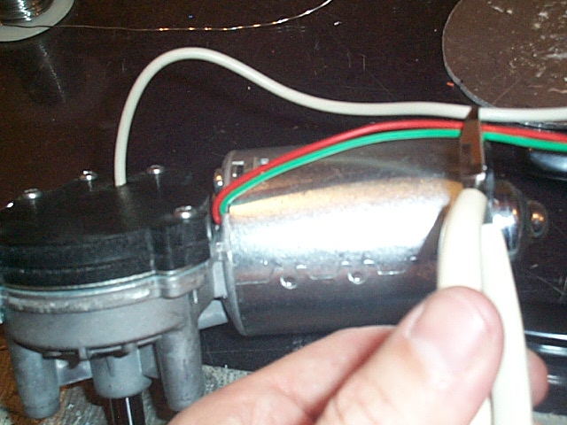
Here's
a shot clipping off the excess wire from the motor and the encoder.

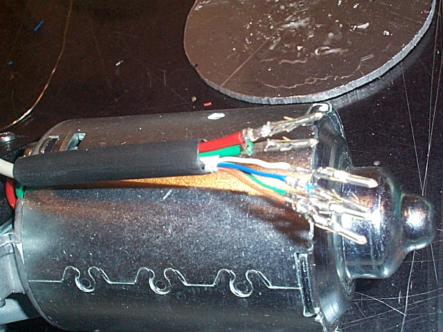
Here's
a shot of the .062 Molex male terminals crimped and soldered
to the wire ends. These snap into the plastic Molex housing.
More
shrink wrap tubing in place before snapping the terminals into
the connectors.

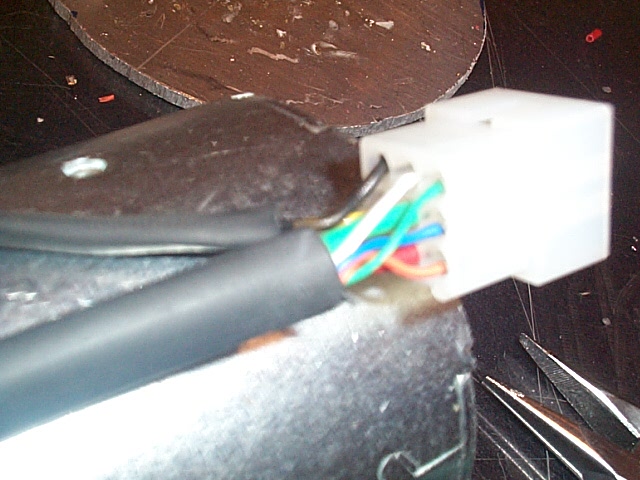
Here
they are snapped into the connector. The holes are labeled
(1-9) but it's very small raised print and hard to see.

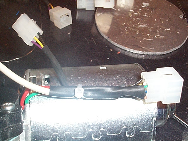
Finished.
Note the shrink tube and zip tie for stress relief.

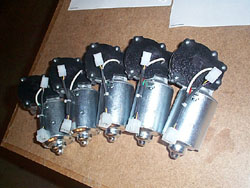
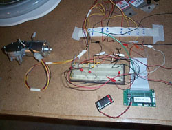
Here's
all five motors with their harness.
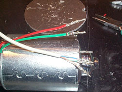
As
always, testing each step along the way is very important.
Here's a temporary setup that allows me to test each motor to
ensure the encoder works and the wire connections are all good.
Previous
Entry Top Next
Entry


 Mike
J. ( B9-0002 )
Mike
J. ( B9-0002 )