Previous
Entry Top Next
Entry
10/29/2004 - Building the Donut Assembly
The
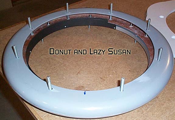
Donut, lazy susan and waist plate form a single assembly. There's
an optical switch and interuptor plate also attached, it is used
to determine the straight ahead position.
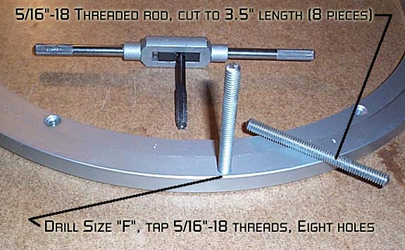
First,
we drill out and tap eight 5/16" holes in the outer ring
of the lazy susan. The outer ring will be stationary and the inner
ring will turn. Eight 3.5" long support rods are
cut from 5/16"-18 threaded rod stock.
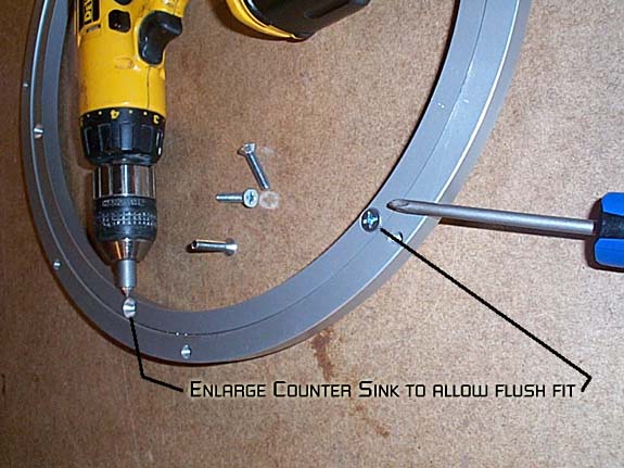
The
inner ring gets six 1/4"-20 holes drilled out and tapped.
Use the six counter sunk holes already present (the counter
sunk side is the bottom).

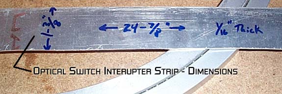
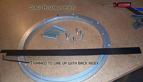
Cut
a strip to act as the interupter for the optical switch from 1/16
aluminum sheet.
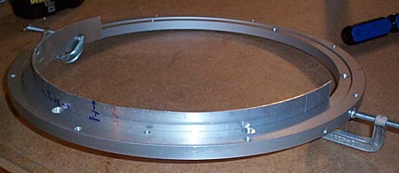
Use
clamps to hold the strip in place, it should be flush with the
top of the lazy susan.

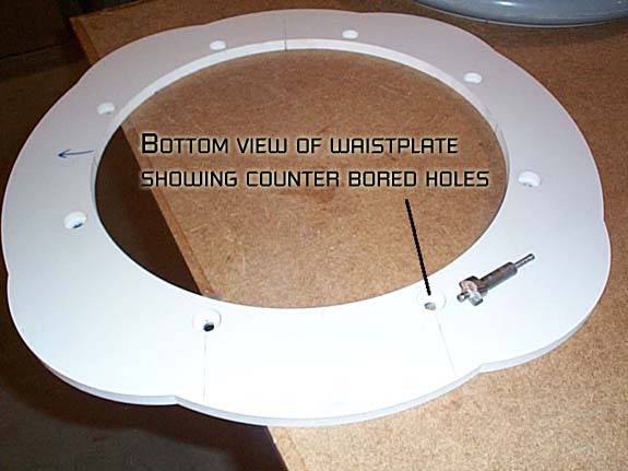
Bottom
view:
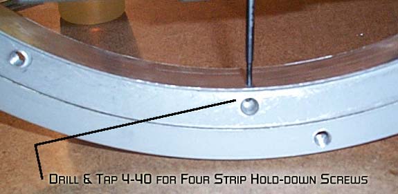
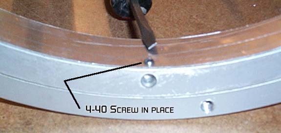
Drill
and tap 4-40 screws. Note how these line up with the unused pre-drilled
holes.
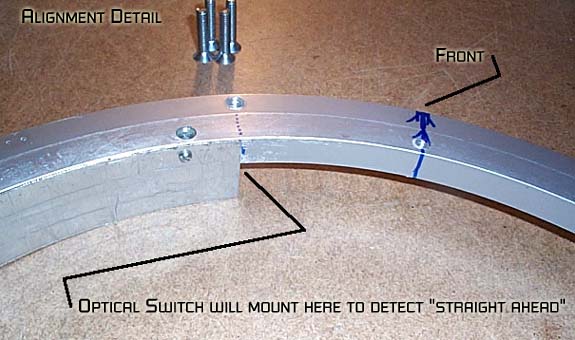
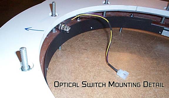
The
alignment is critical. The leading edge of the interuptor should
line up with the support post as in this photo.
After it's mounted trim the trailing edge to be exactly 180 degrees
offset. Paint it flat black to reduce reflections that might
cause false signals.
Here
are all the fabricated parts prior to assembly
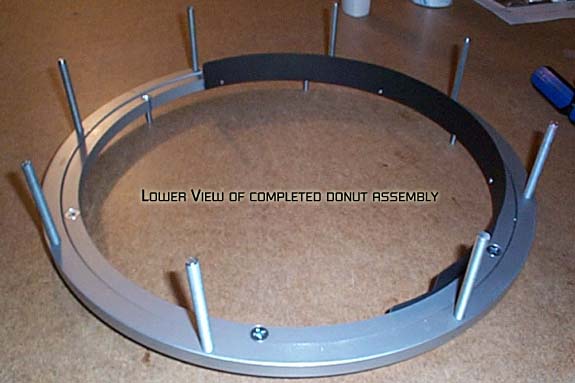
Lazy
Susan assembly complete: Top View

Bottom
View
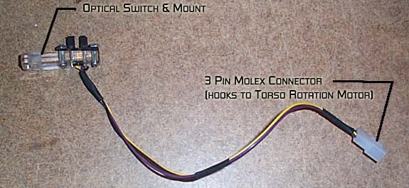
Here's
the optical switch with a fabricated mount made from a 1/4"
piece of acrylic.
Here's
a shot of how the switch interacts with the strip.

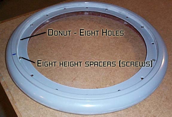
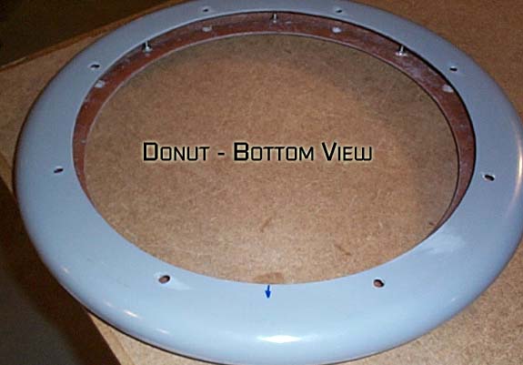
Here's
the donut with 8 hole drilled to allow the 8 threaded rods to
pass through it. Also, 8 screws are in place to act as spacers
to raise the lazy susan to the correct height.
Here's
the waistplate with 8 holes drilled for the support rods. Note
the counter bored holes to allow for nuts that are flush with
the bottom of the waist plate.
Lazy
susan in place in the dount.
Waist
Plate in position, held there by nuts on the threaded rods.

Optical
Switch Mounts on threaded rod.
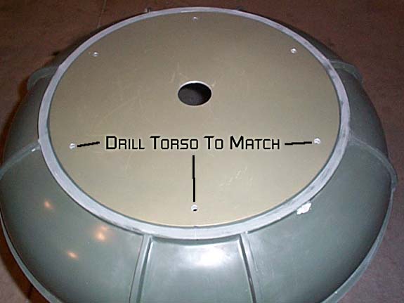
Central
Support Structure (CSS) bottom plate. Fabricated from 1/8 aluminum
plate.

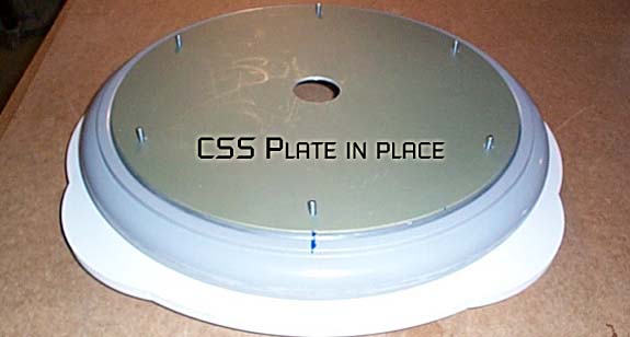
Drill
the torso to match the CSS plate.
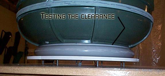
Make
sure the torso rotates without binding. There should be about
1/16" clearance between the torso and the donut.
That's
it for now!
Previous
Entry Top Next
Entry


 Mike
J. ( B9-0002 )
Mike
J. ( B9-0002 )