


 |
|


| Robot Reference->Power Pack Info | |||
Power Pack Replica Project
After restoring my Librascope Power Pack last year (see that story in my previous post), I still wanted to make a highly detailed and accurate replica to stand-in for my rare piece when at a convention or other public event. No small task, I must say! Click On Any Picture for a Larger Image
Over the past 20+ years I have been collecting Power Pack parts and have managed to find all the original components, the original connectors, and I was even lucky enough to get a NOS Librascope frame from Chris Pappas who by some miracle found about 20 of them back in 2016. I must also give some big props to Gregorio Padin who found many of the rare hard to find components and connectors. I had all the pieces to build a completely authentic Power Pack replica... Except one... the board. 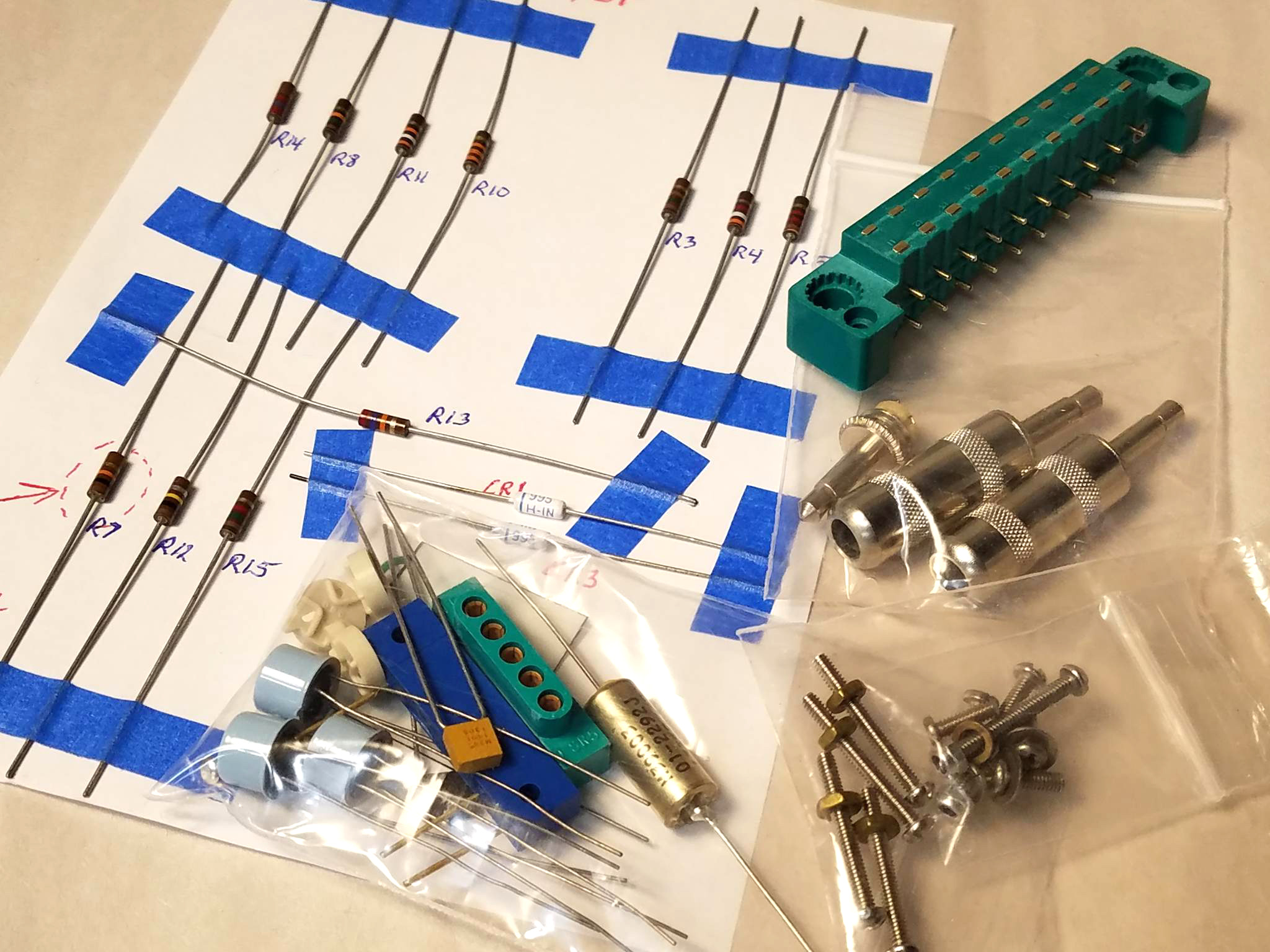
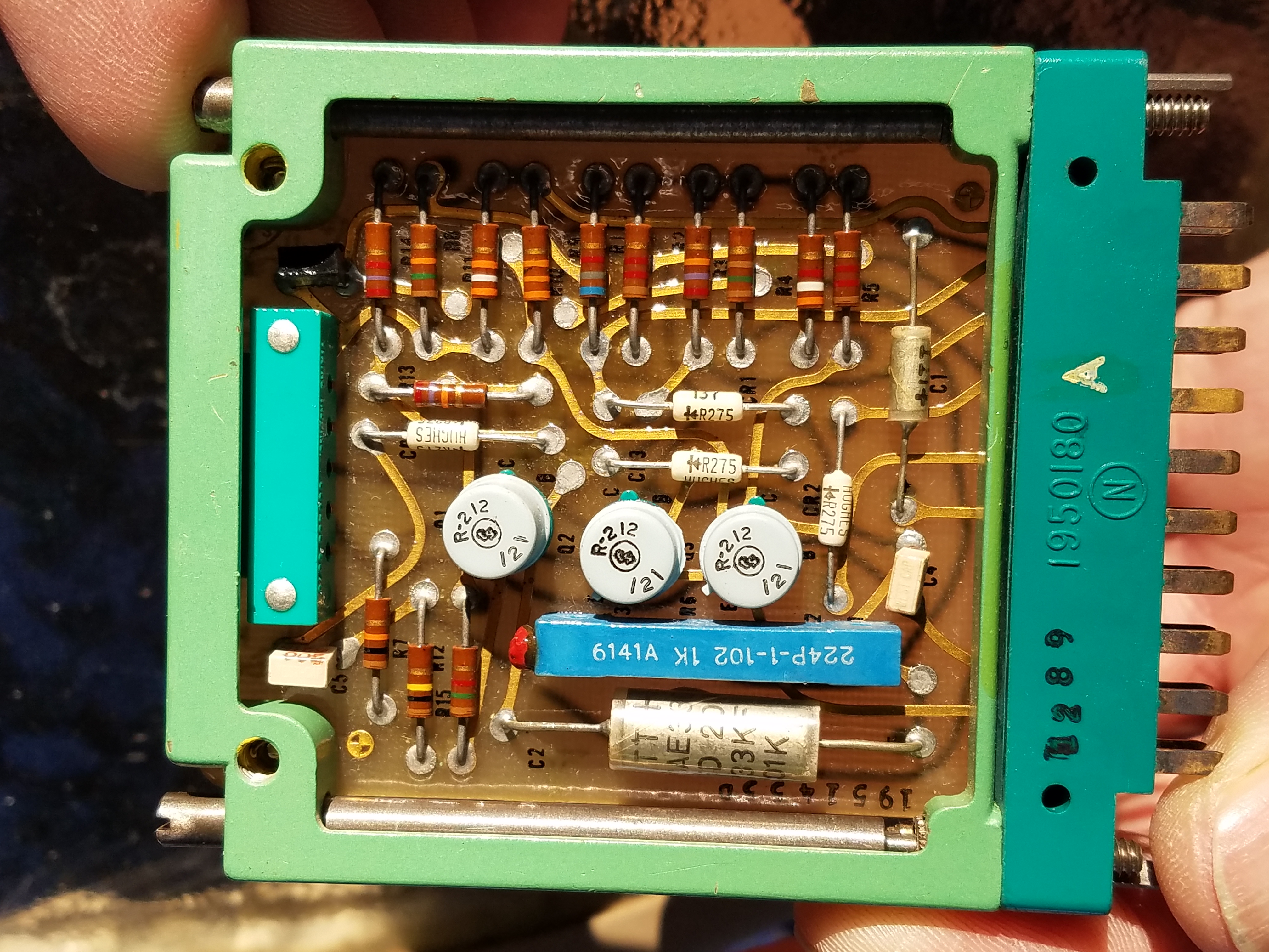
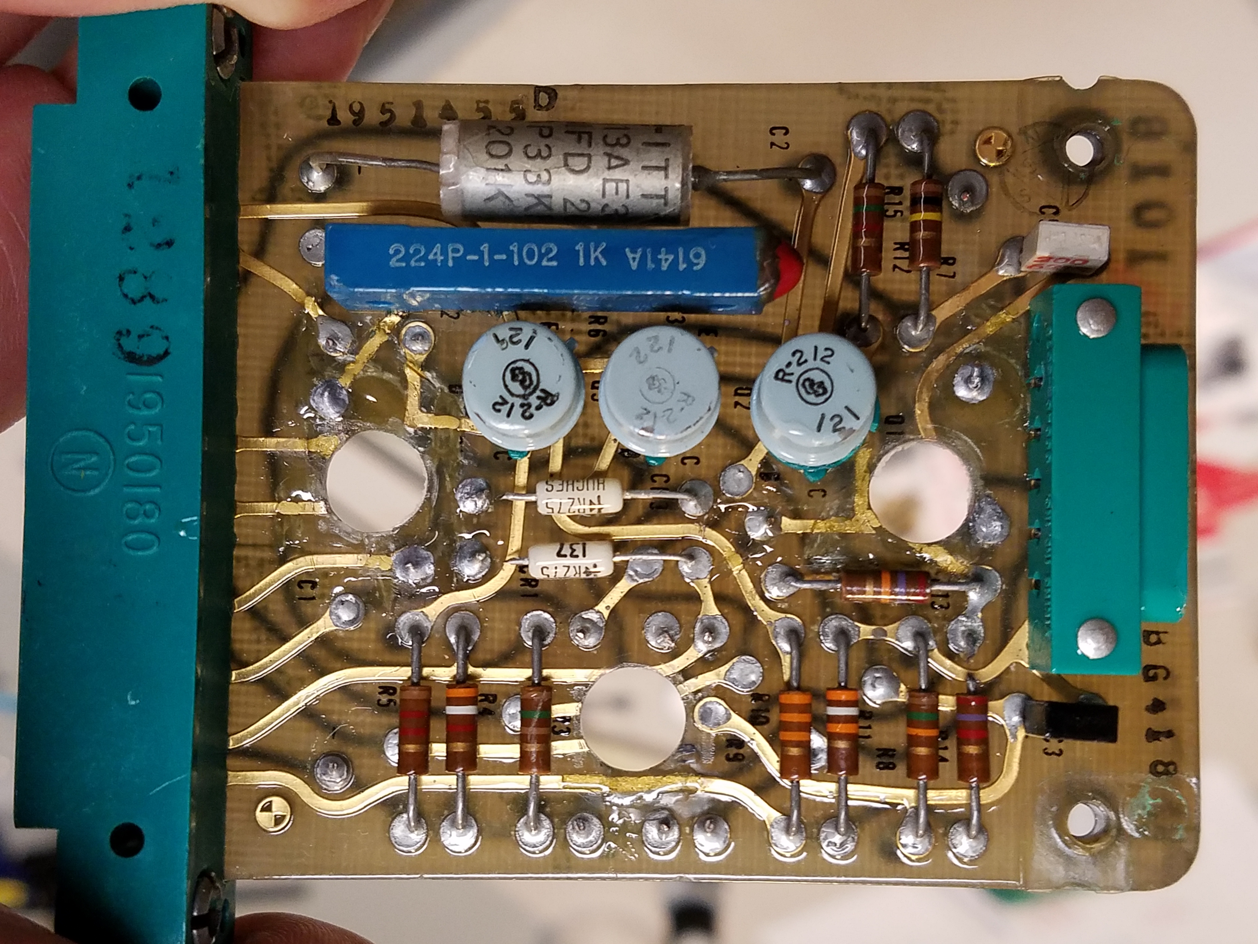
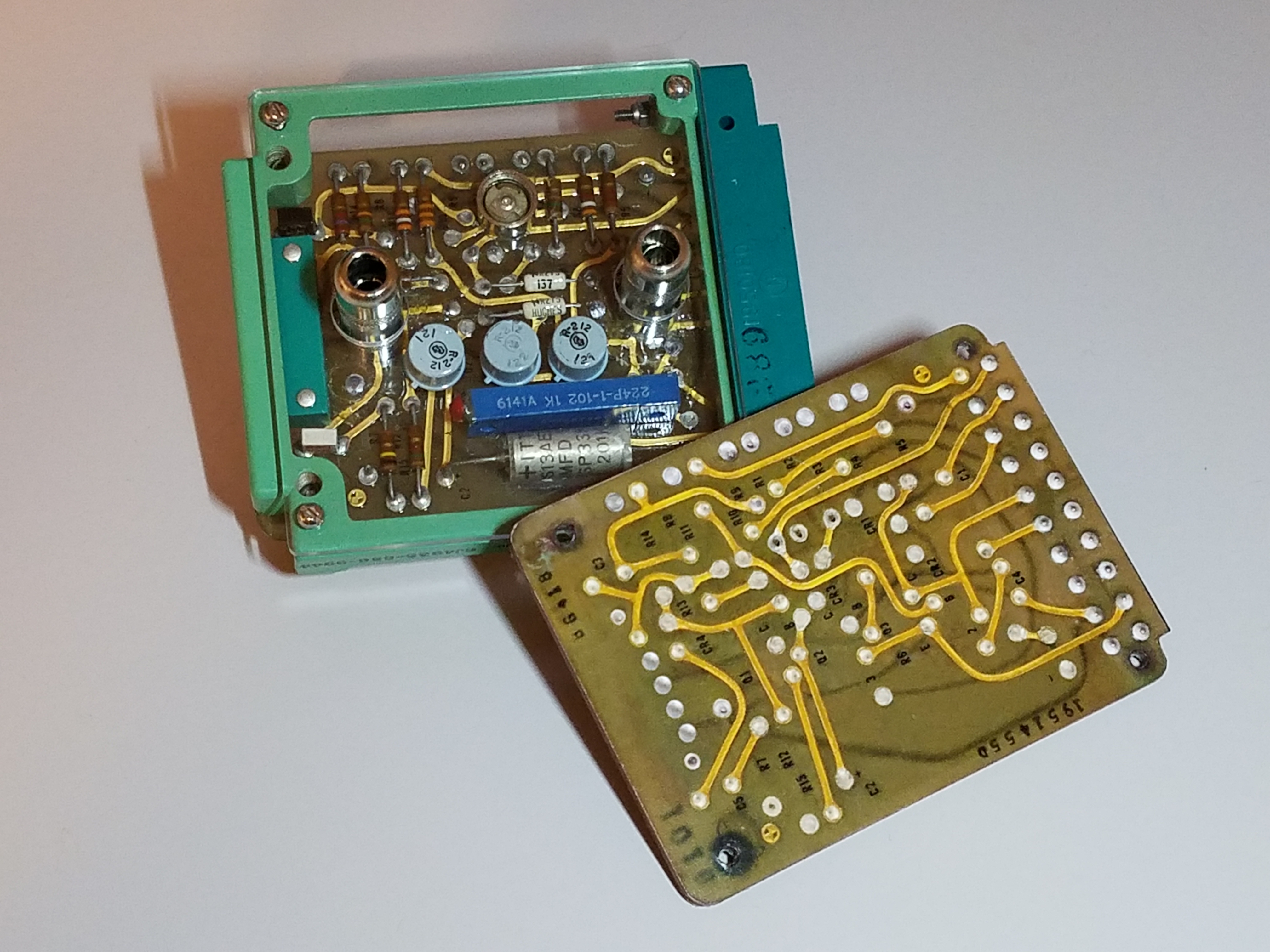
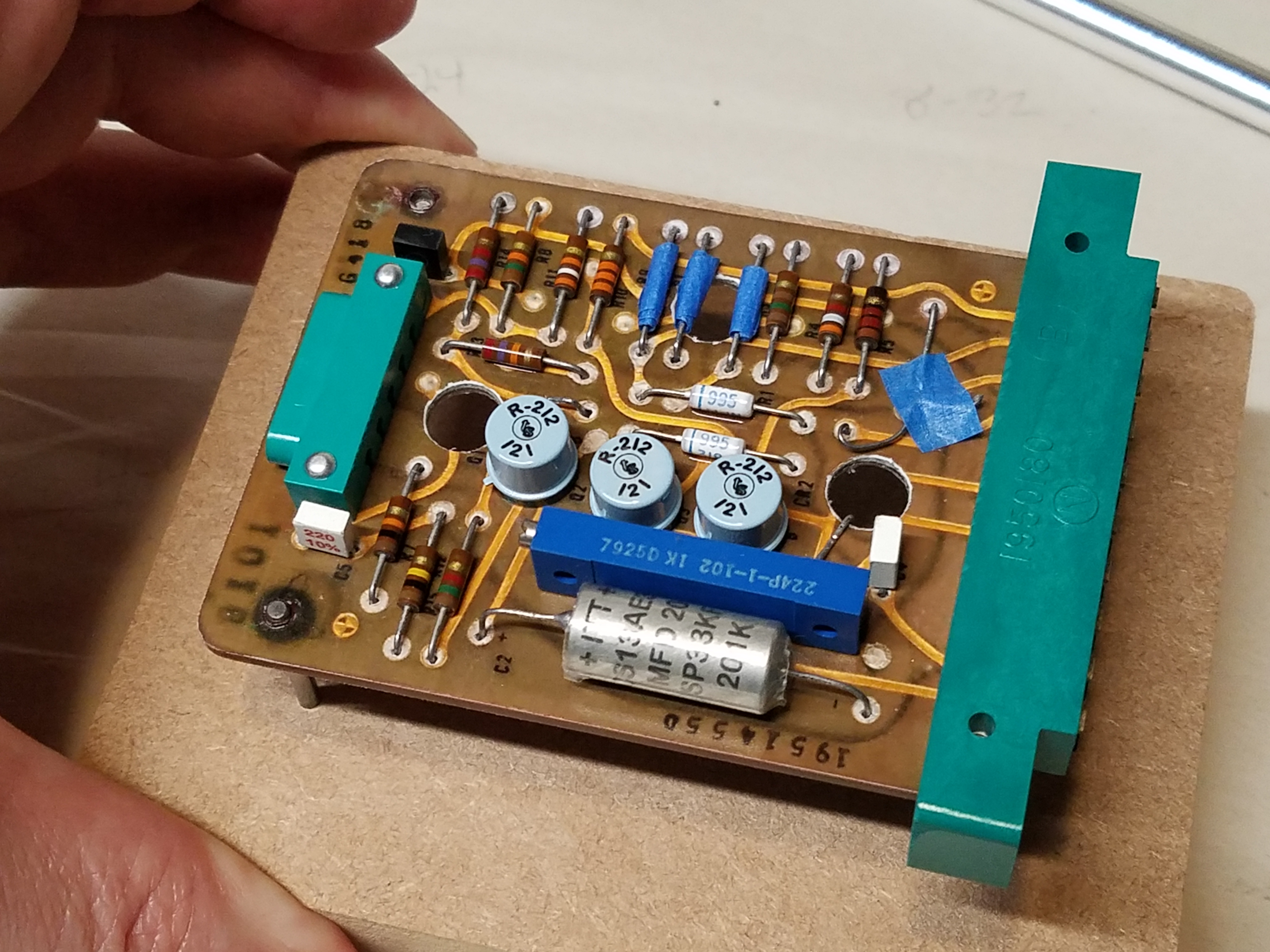
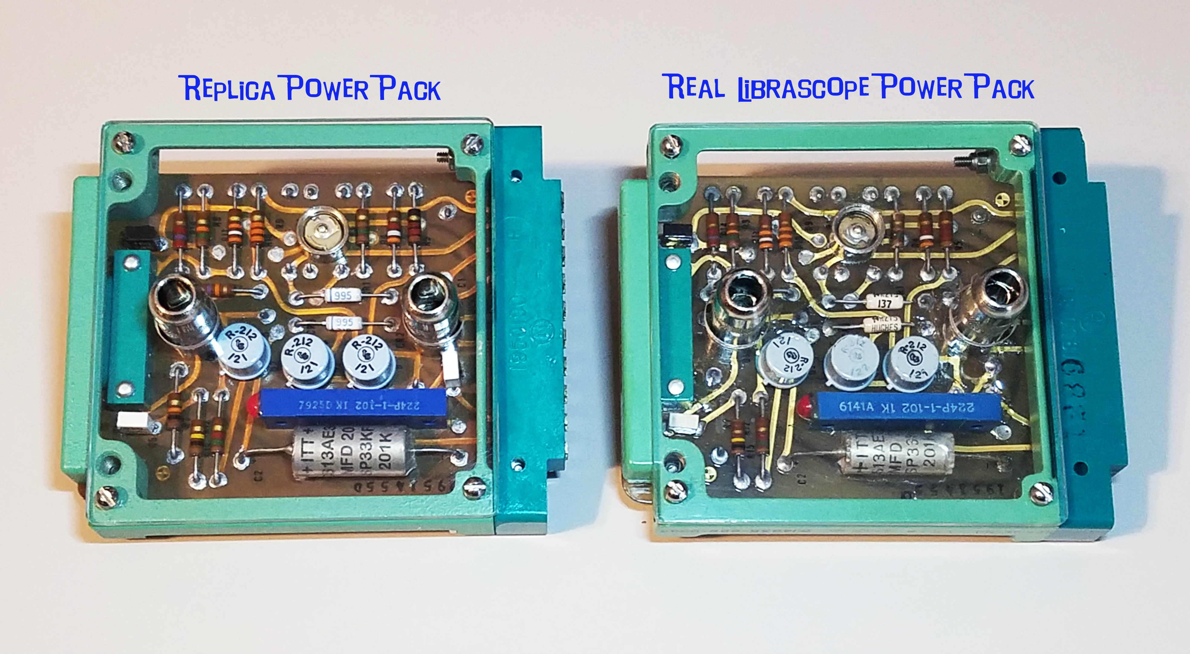
The board... Yes, the board. There are some replica boards out there, but I really wanted a highly authentic looking board with gold traces and all the markings of the original. To me those details really pop on the real piece. Many builders over the past 10 years have claimed they could and would make one, but none have come through. I thought about tossing all the parts back in a box on a shelf until an authentic board became available, but would that ever happen? I figured I needed to take matters into my own hands... but how? Well, I had an idea... really born from my experience restoring the Librascope board. I had some great reference pictures of a real Librascope board, both my own, and Brian Mix's unmolested Librascope card which he generously brought to Wonderfest in 2018. What if I took those good photos of the board, size corrected them in Photoshop, then digitally removed the components? Maybe I could create a photographic blank board. Then I could glue the photos to a piece of aluminum or something like that to make a very realistic, detailed "faux board"? I had to give it a try!
I opened Photoshop and got to work. I had to painstakingly recreate all the traces and text labels that were hidden by components in the photos. One full week later (this was a LOT of work!) I had my blank board, both front and back. I was really happy with the results, but believe me, it was a job! 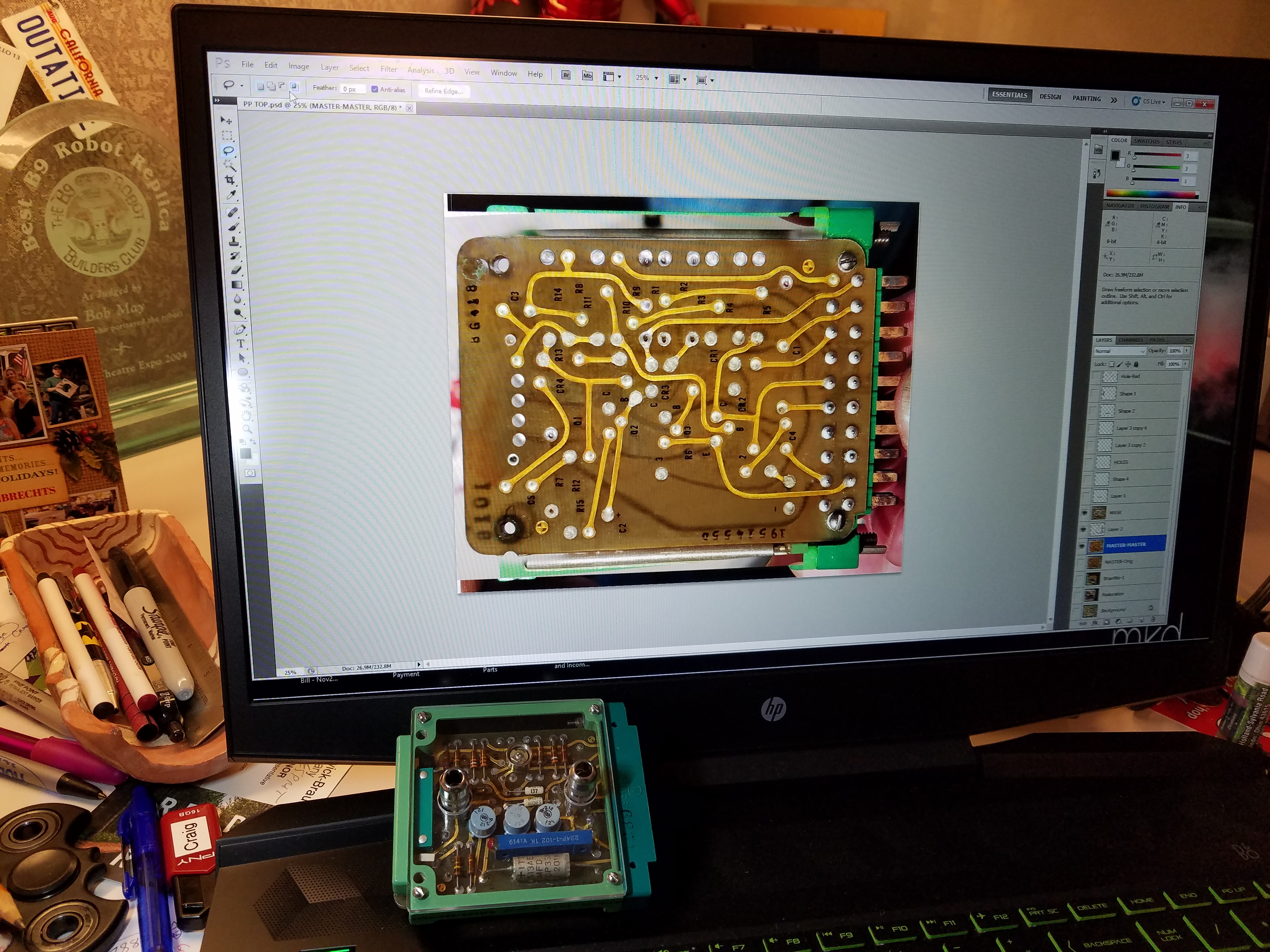
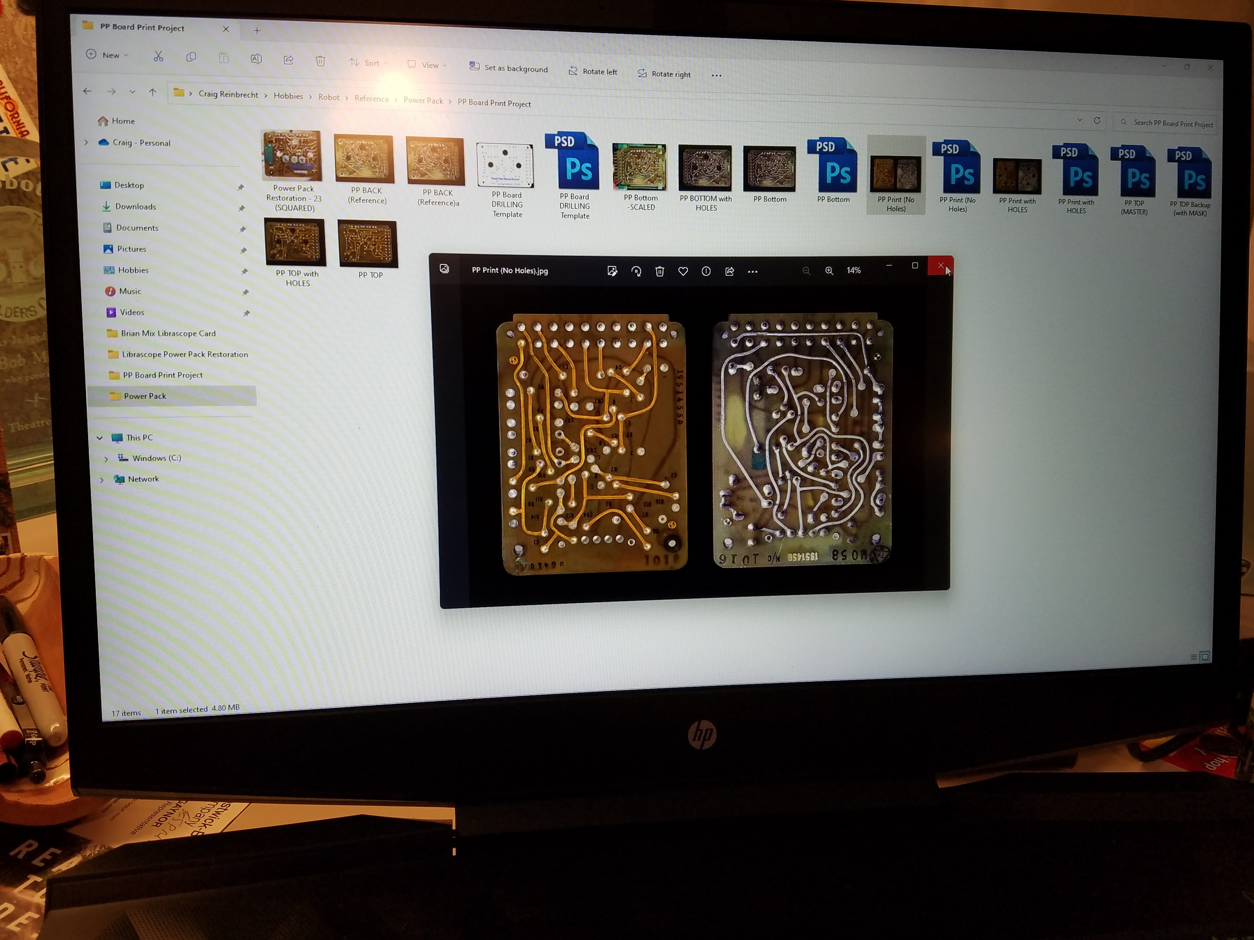
I sent the photos up to Walmart because their printing process is much better than any consumer inkjet printer, and ultimately cheaper. Even though I sized the pictures precisely, I found Walmart zooms in slightly so the size was off. I carefully and precisely calculated how much, resized my photos and tried again. This time they came out perfect! I actually had the beautiful blank board photos in my hand. Now the challenge was to get the photos glued to a piece of aluminum and aligned perfectly front to back. 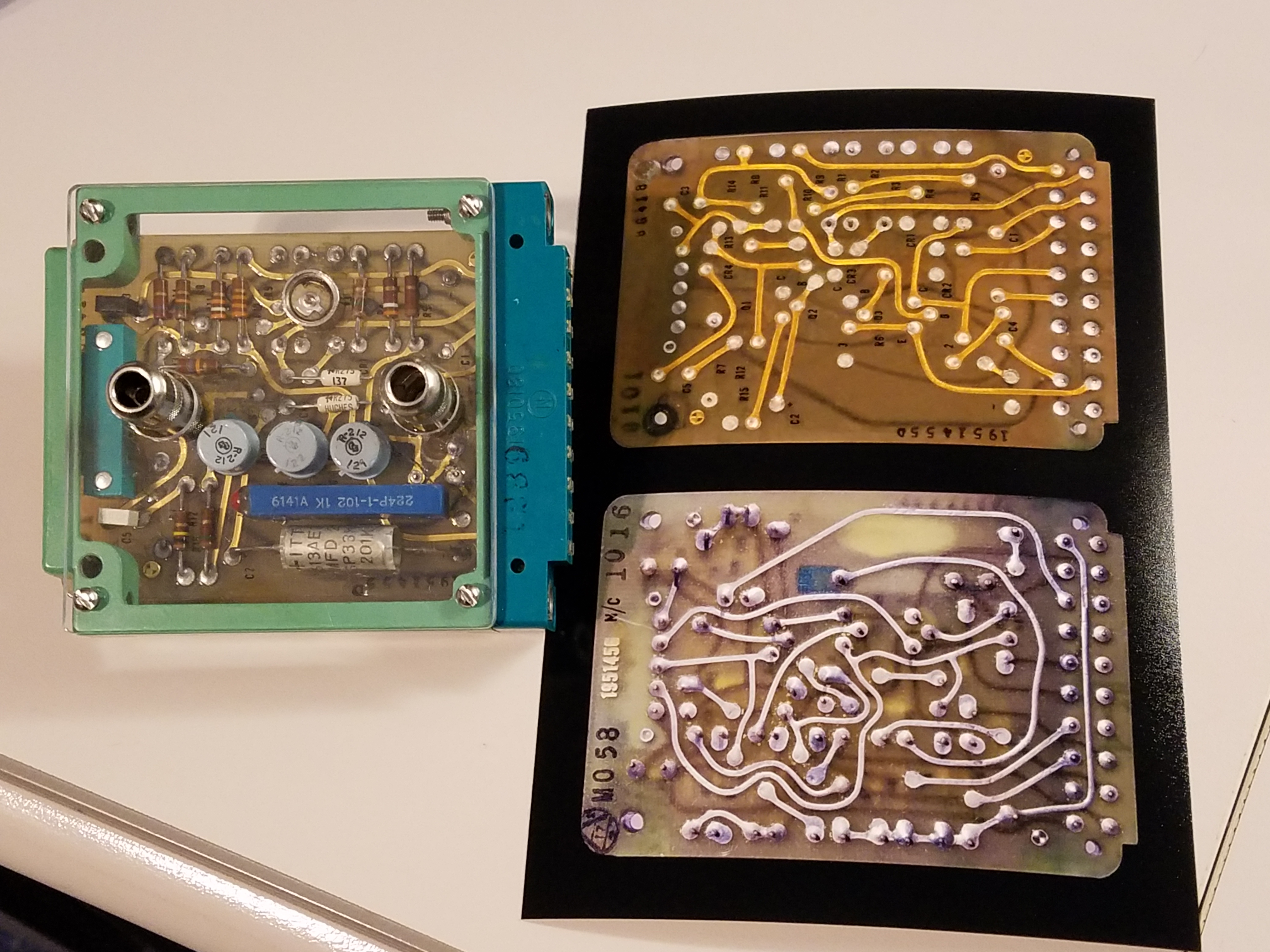
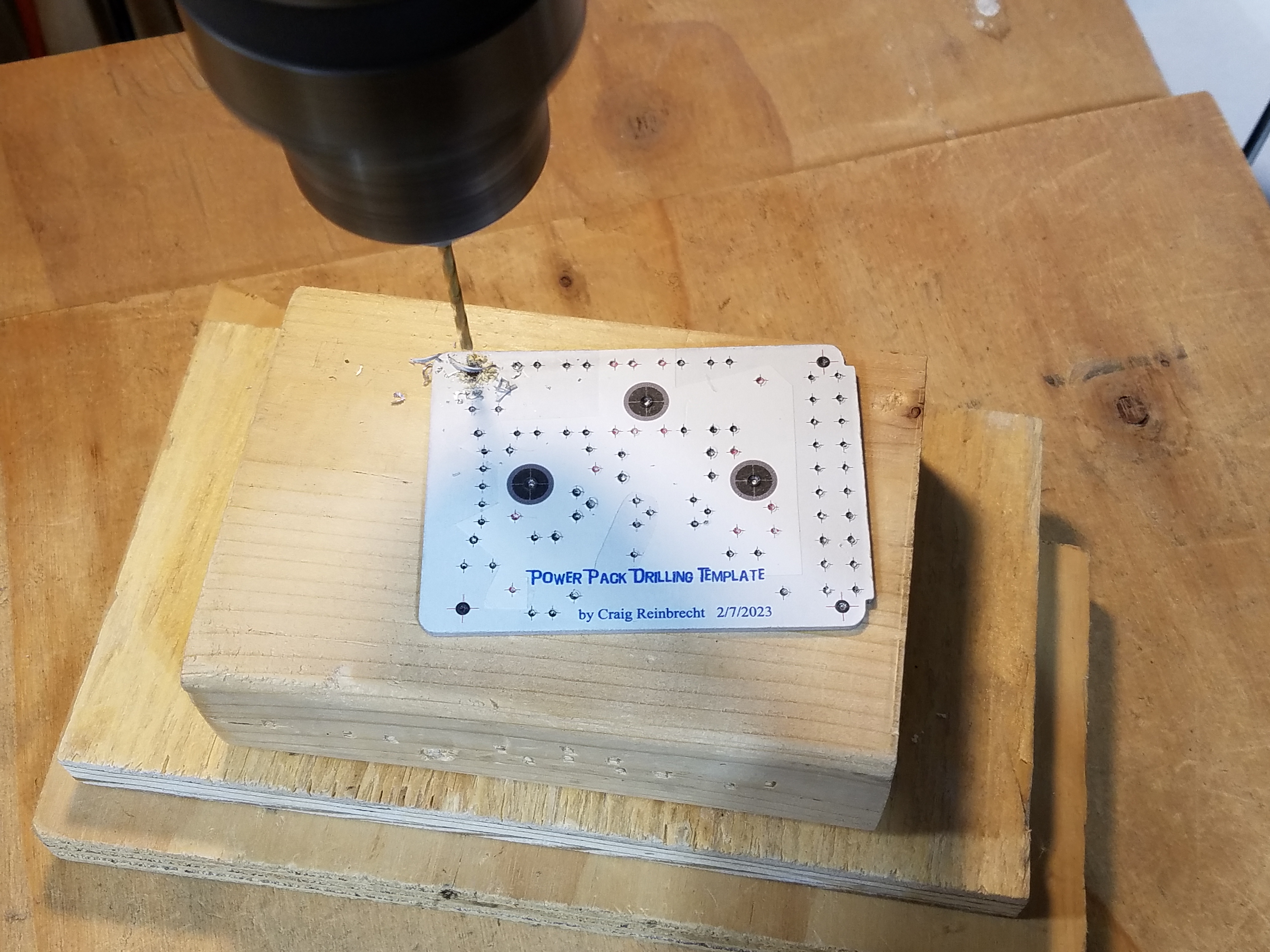
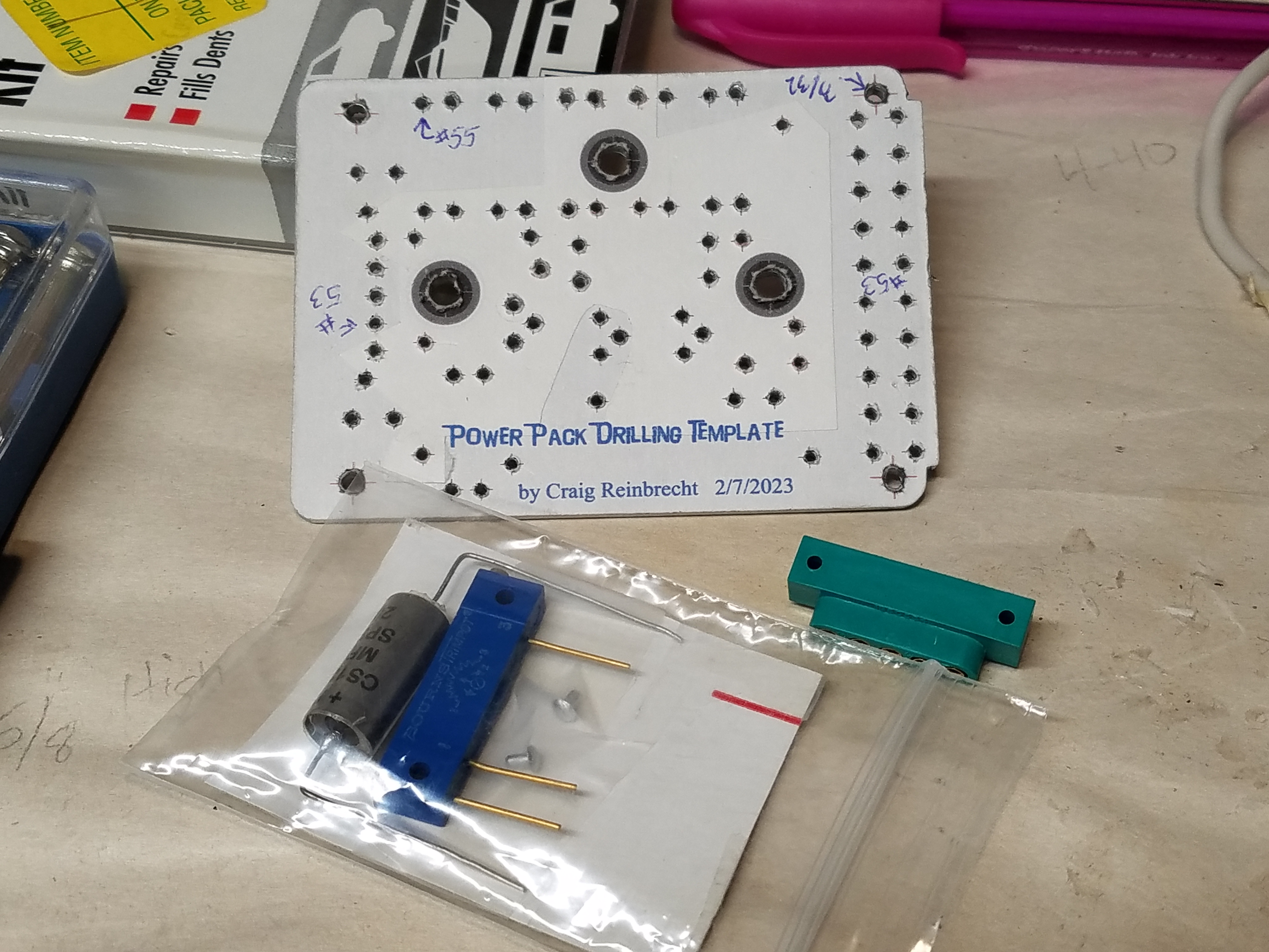
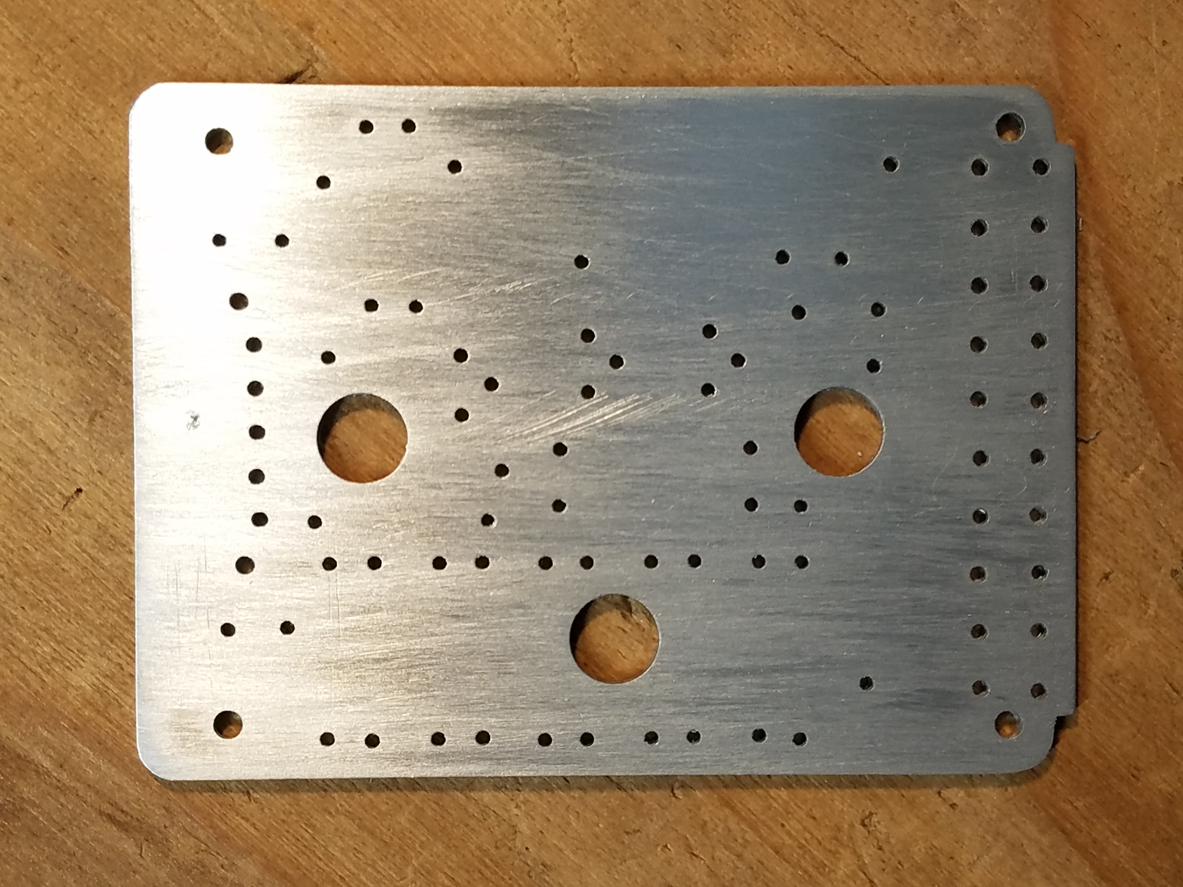
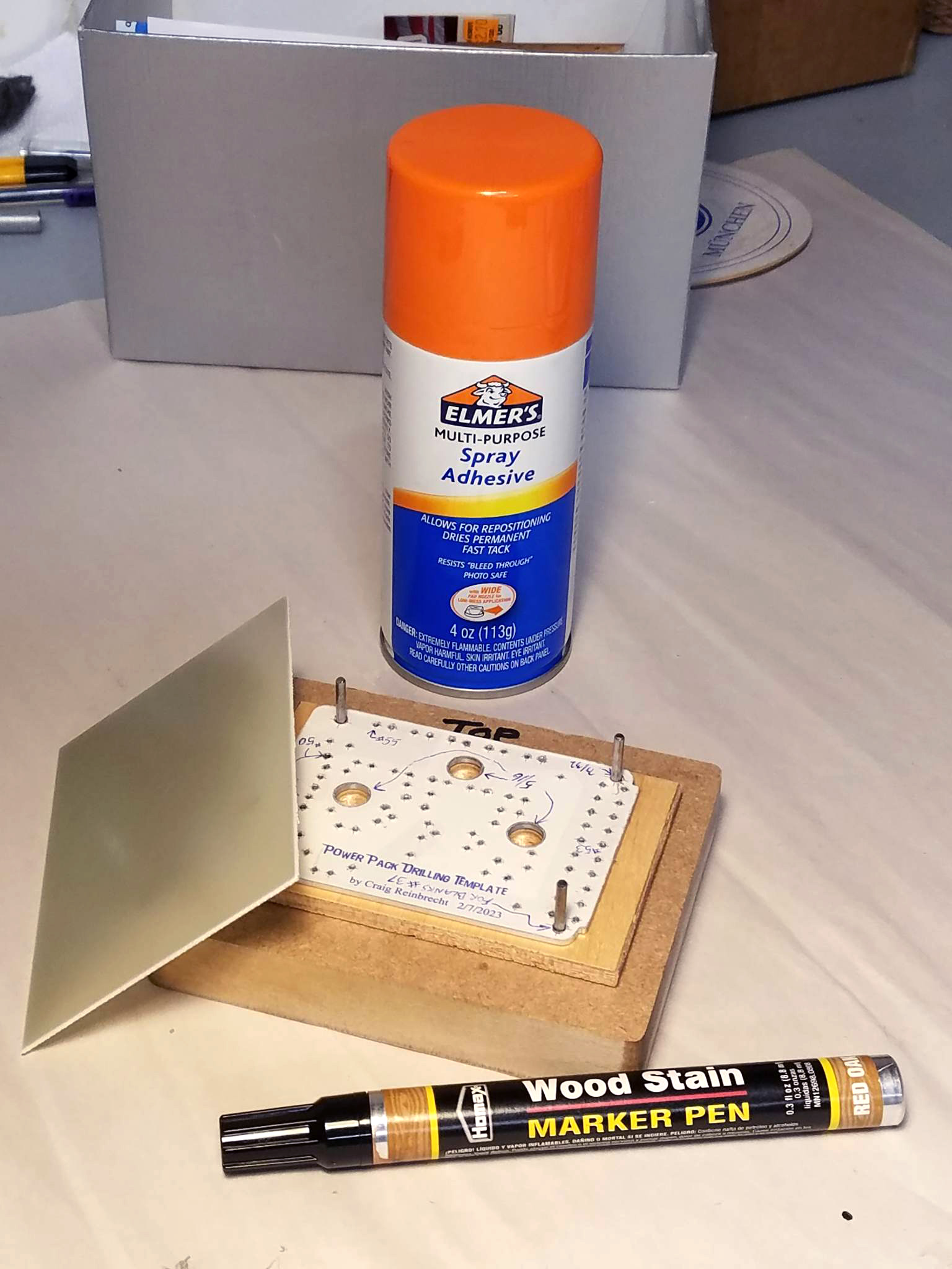
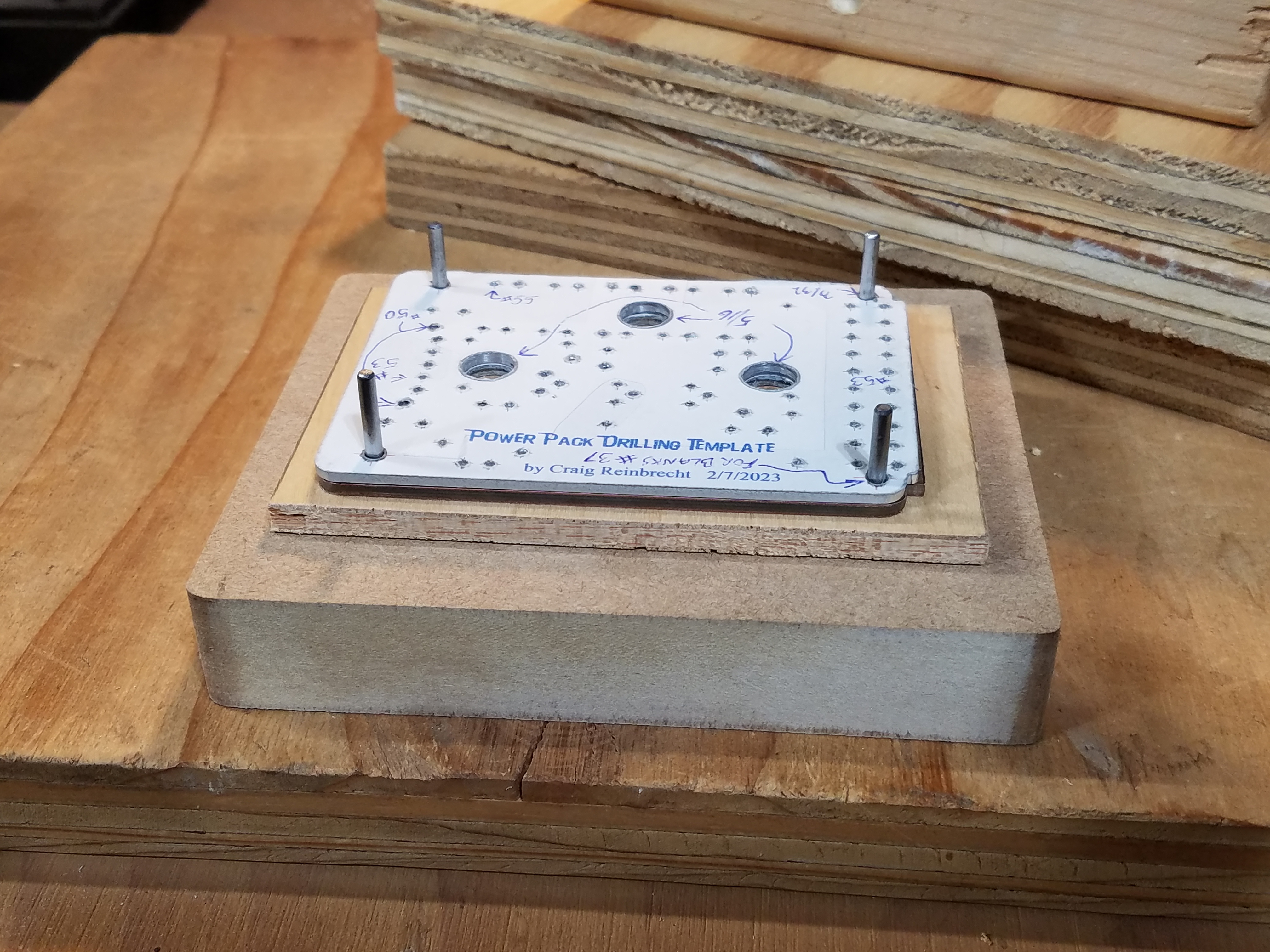
I decided it would be best to cut the aluminum to the outside dimensions, and drill all the holes for the components before gluing the photos to it. To do that I created a "drilling template" I could print on adhesive label paper. After printing I stuck it on the aluminum, carefully trimmed the sides, and then drilled all the holes. With this blank aluminum board, I could also make an alignment jig using the 4 corner mounting holes. The jig would allow me to align the photos as I glued them on.
However, as I worked on all this, I came up with a better idea. I had a piece of PCB material in the correct thickness, so why not use that? It is supposed to be a PCB, after all. Then I could use my aluminum piece as a jig, to drill all the holes. Once I drilled all the holes and trimmed the outside edges of the PCB, I was ready to finally glue my photos. 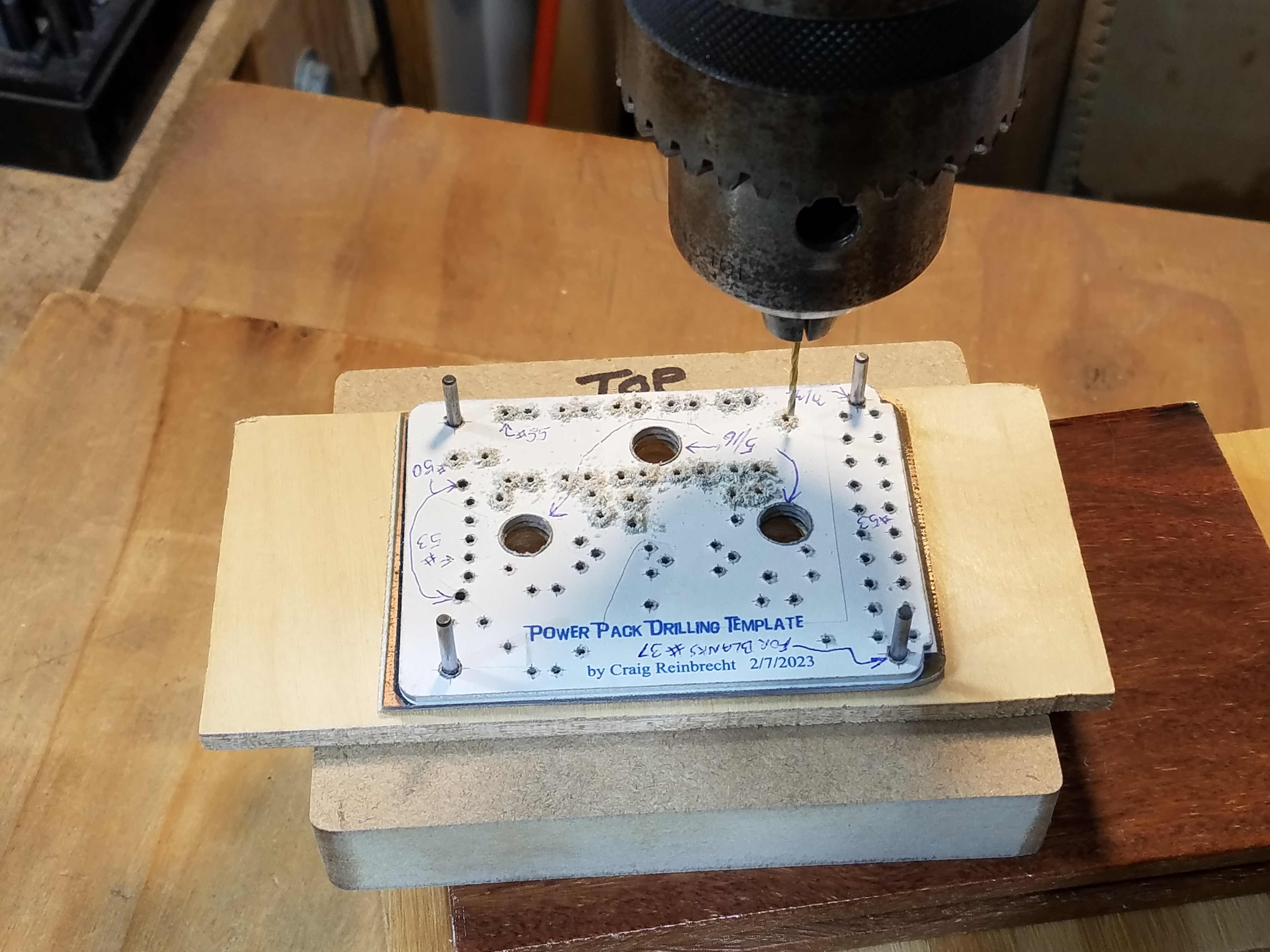
First, I used my aluminum jig to drill the 4 corner holes precisely in the front and back photos. Then I used Elmer's spray adhesive to glue it to the PCB using my jig for alignment. I trimmed the edges of the photo with an Exacto knife, and sanded it a bit for a nice flush edge. To hide the tiny bit of white on the edge of the photos, I used a brown stain pen I had laying around for wood touch ups around my house. That all worked great, and I now had a blank board! Wahoo!
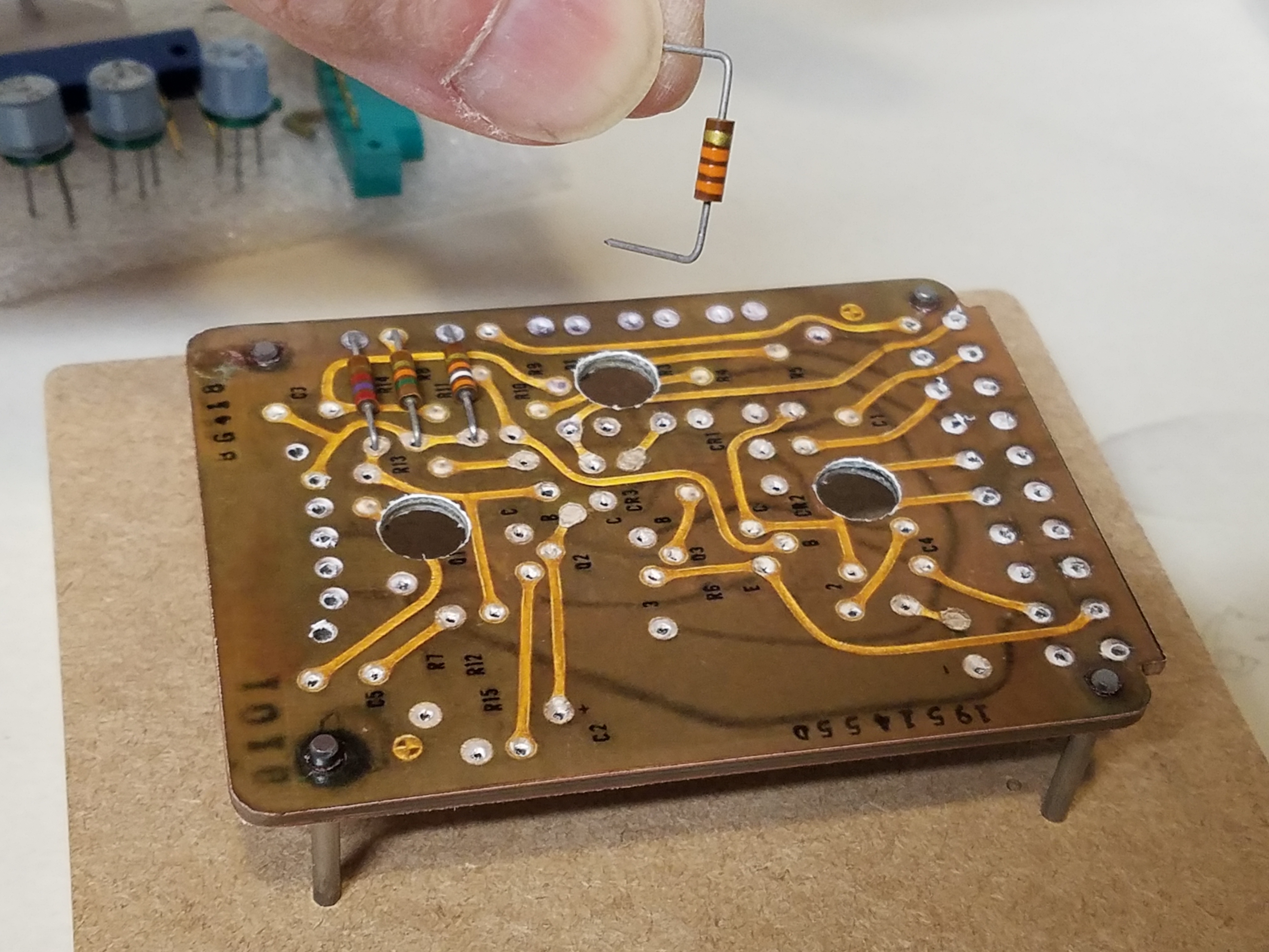
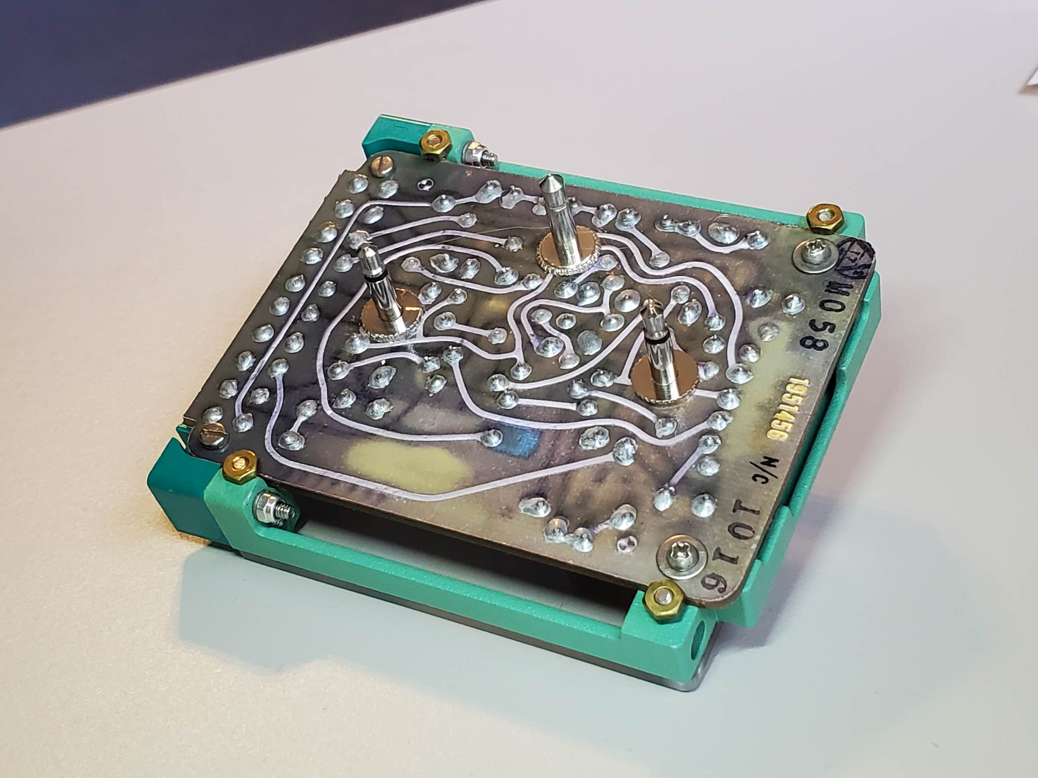
You might be asking... "Well how the hell are you going to solder components to this faux photo board??" Well... If you recall from my Librascope board restoration, I used clear epoxy mixed with silver acrylic paint to mimic solder in a few spots. For this replica project I would just "faux solder" ALL the components with my silver epoxy mixture. Besides, the Power Pack doesn't actually have to work. It was an idea... and I wasn't sure how well it would work, but it was crucial to the success of the whole project. To prepare the board, I used the aluminum jig to drill out the holes for the connectors, then just used a small nail to poke the component holes through the photo on both the front and back. Remember, the holes were already drilled in the PCB below the photo. I stuck the components into the board using a very tiny bit of clear epoxy (Important tip: use a 30 min. set time epoxy) on the bottom side of the components to adhere them to the board. This held them more secure and prevented anything wiggling out of place while I applied my fake solder.
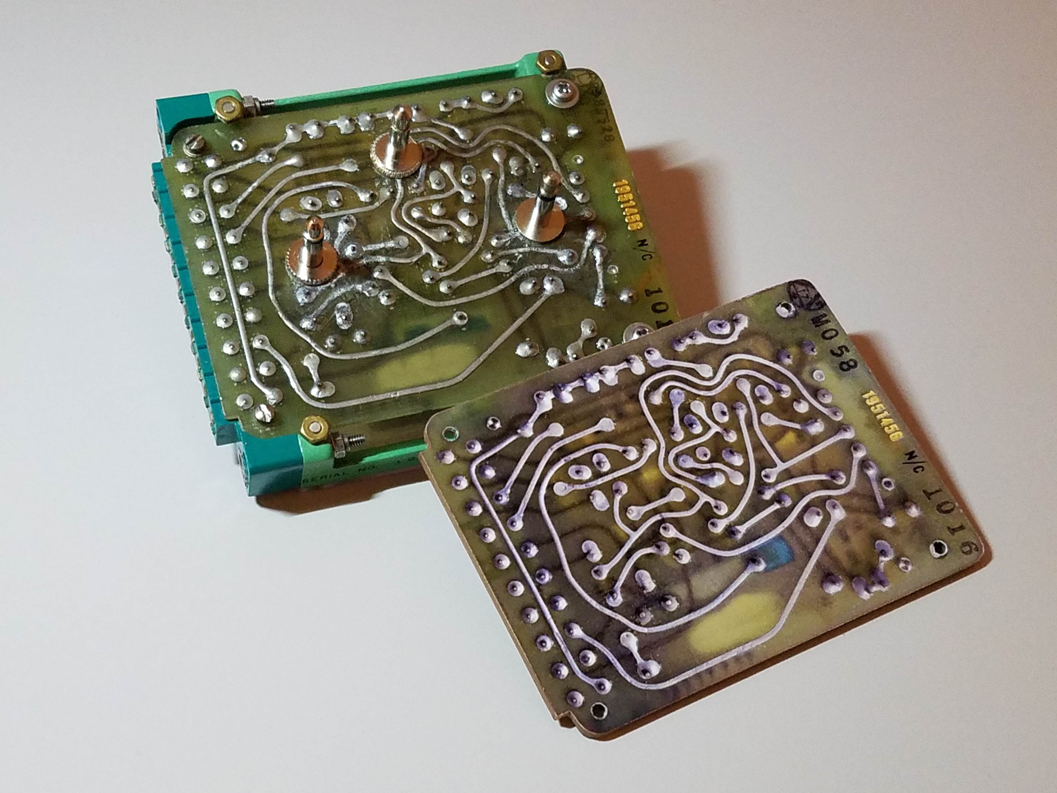
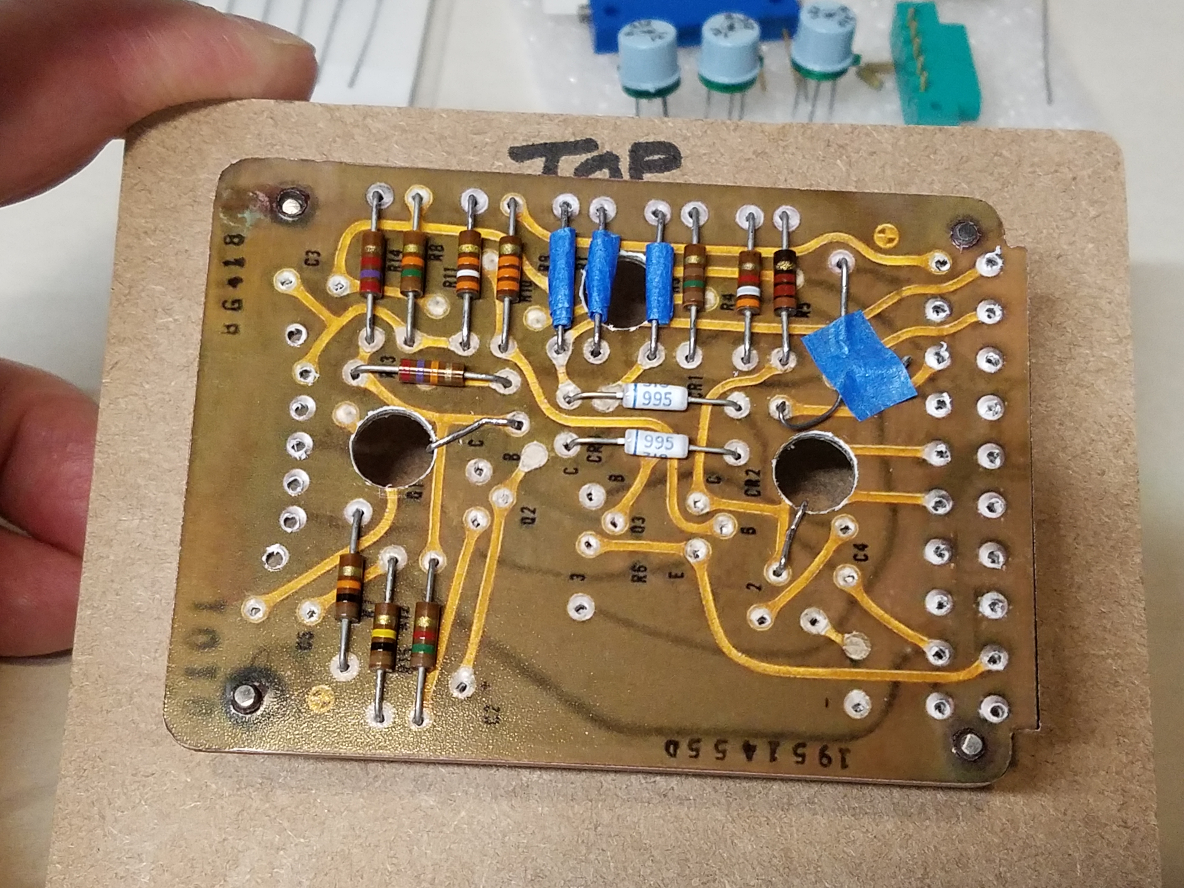
With all the components glued to the board it really started to look like something! After trimming all the leads on the back side, I made up my silver epoxy and started to apply it to the solder spots with a toothpick. This was really tedious! I had to be really careful, because the epoxy is gooey and wanted to cling to the toothpick and dribble all over as I moved the toothpick. Even though I used a 30-minute epoxy, it gets thicker as time goes on and more difficult to apply. So, at some point you just have to stop and mix up a new batch and continue. Eventually, I got the hang of it and managed to finish the backside of the board with only a couple tiny mistakes. Amazingly, it looks pretty realistic! 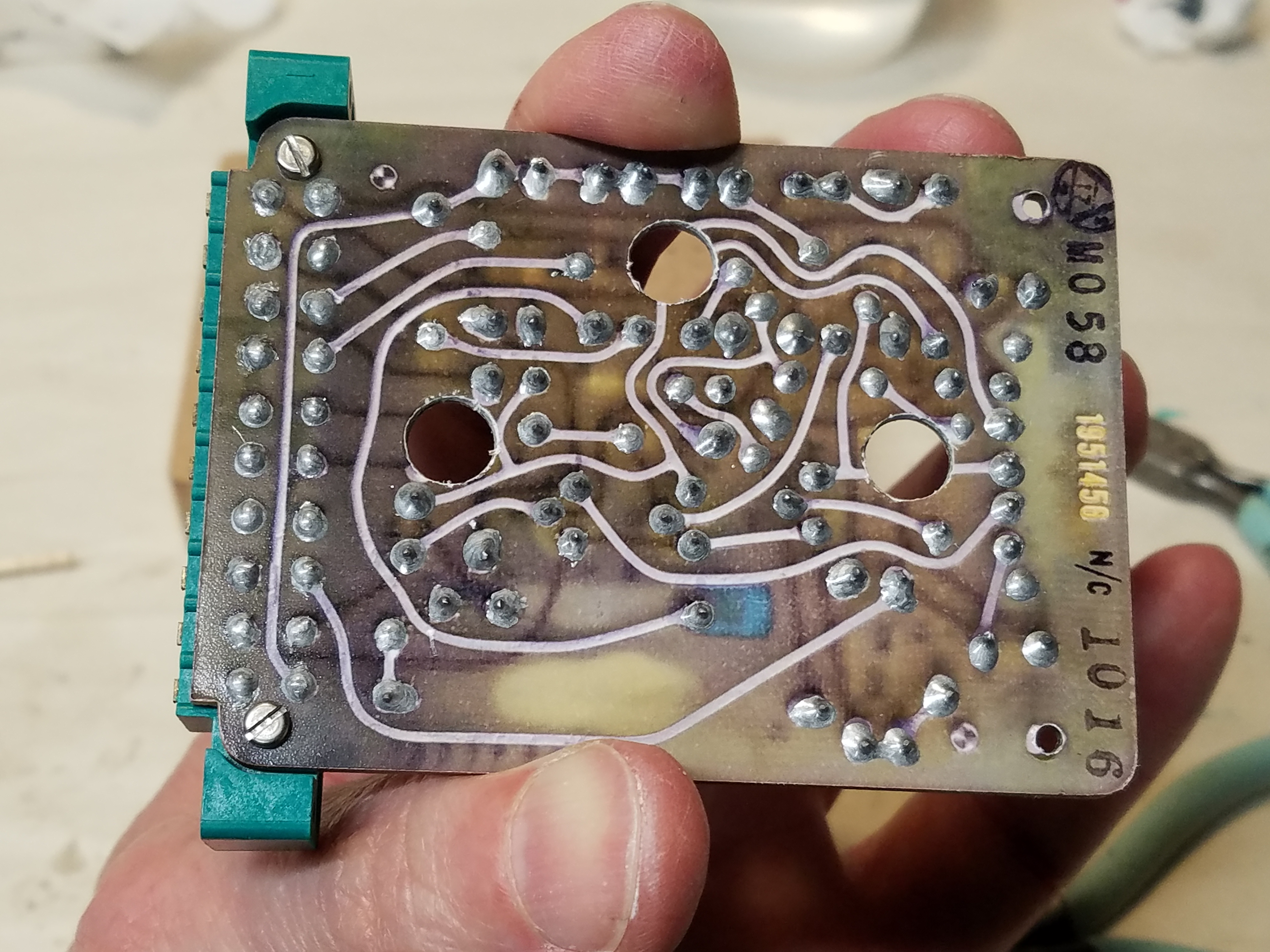
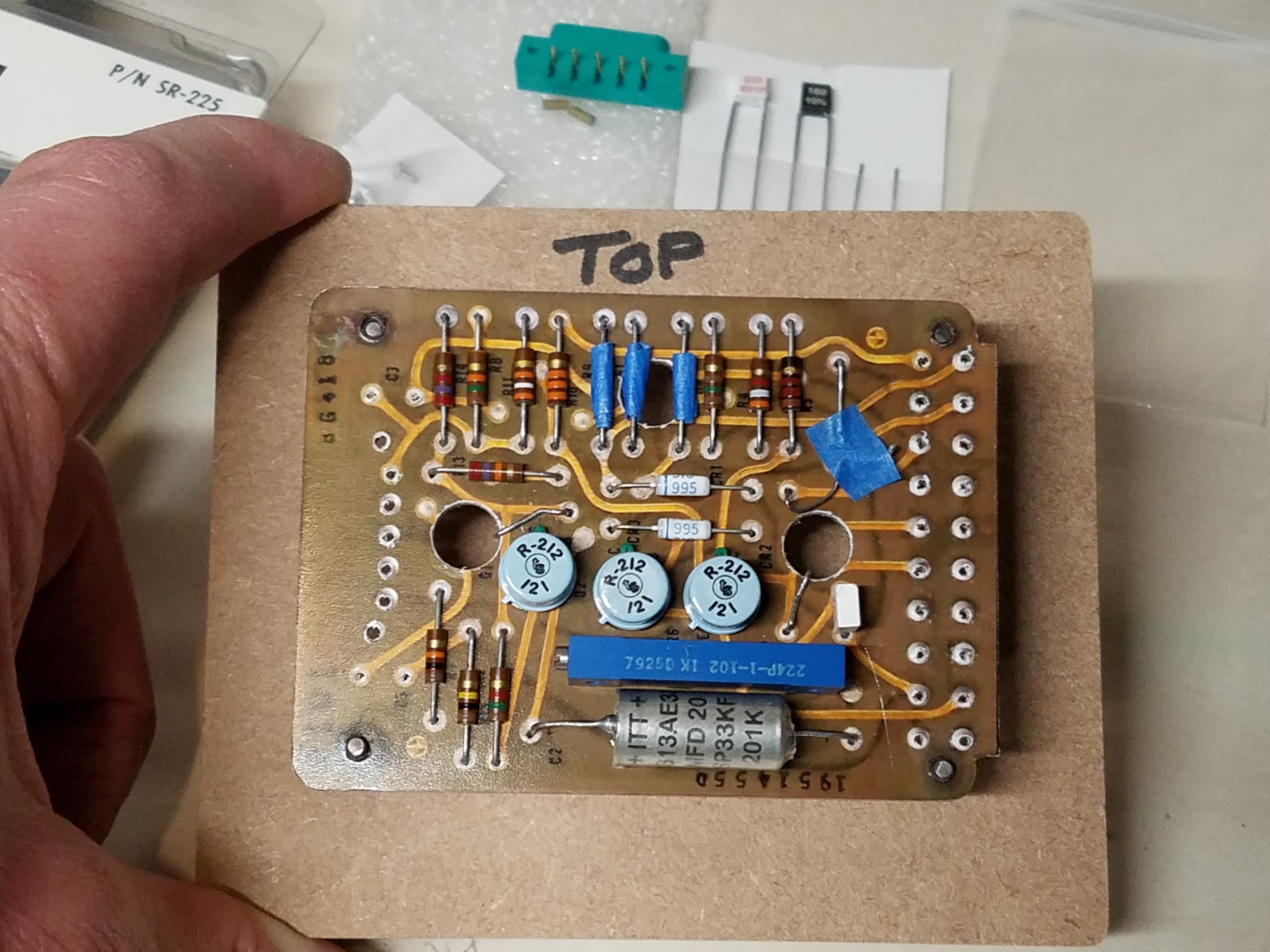
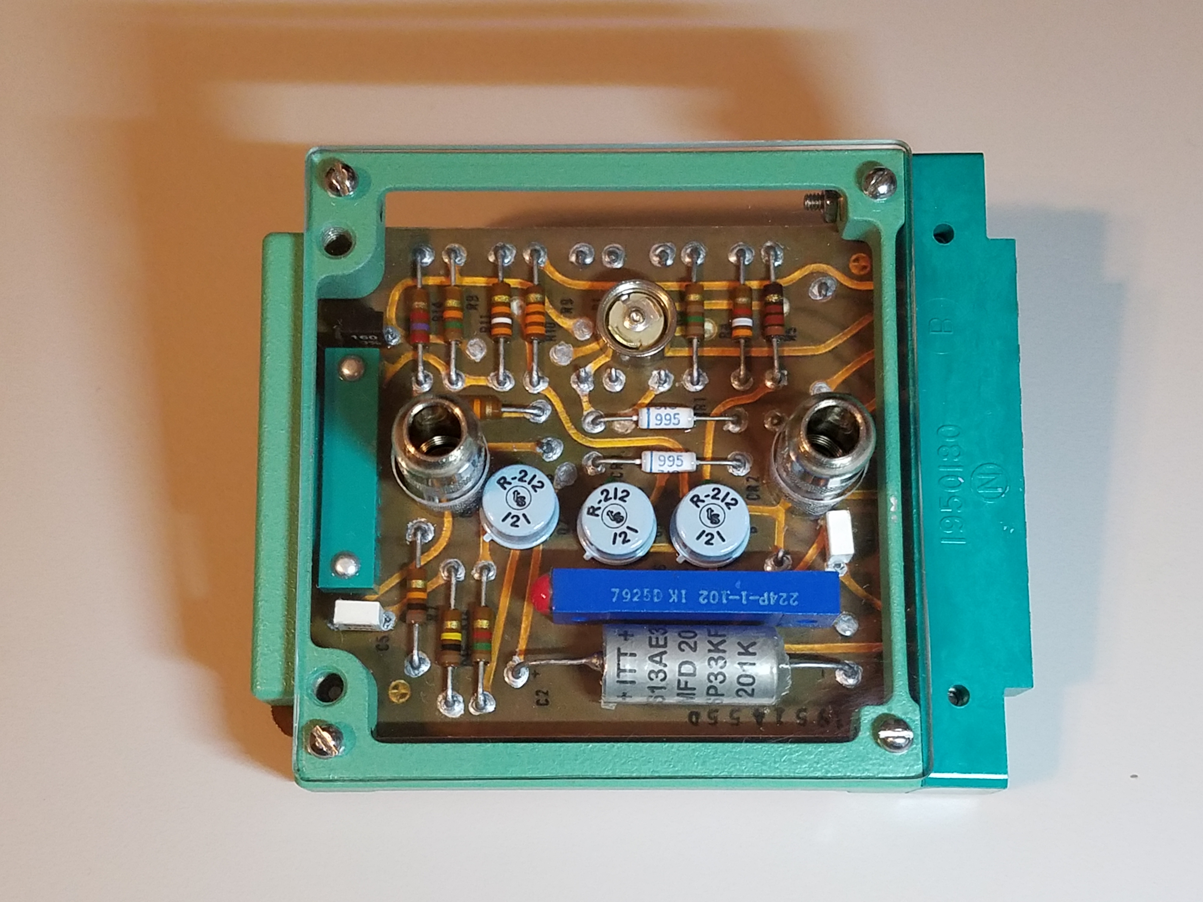
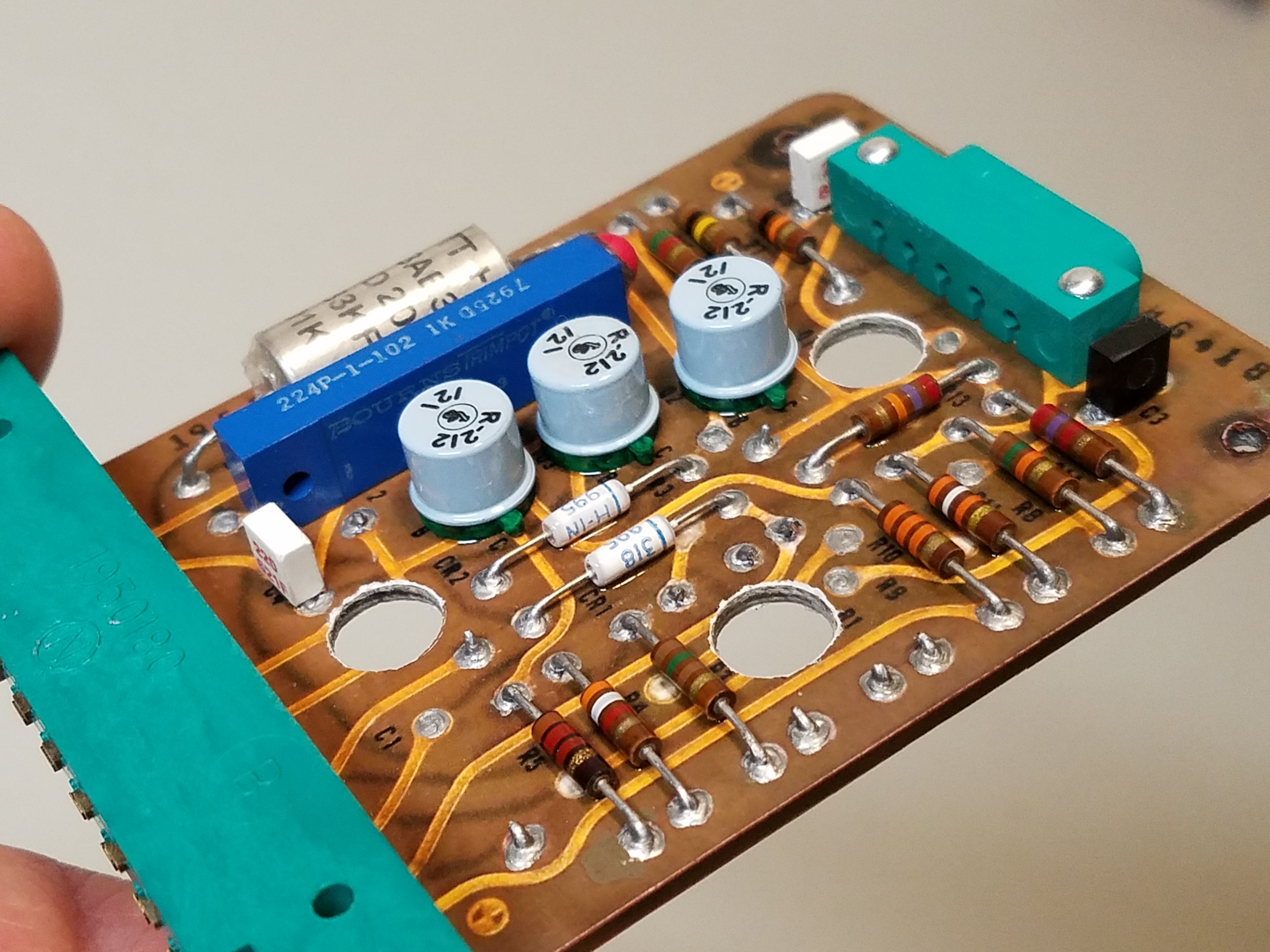
On the original Librascope card (as with most PCBs) there is solder that bleeds though the component leads to the front side of the board. Without this, it just looks a bit naked and not quite right, so I needed to add "solder" to each solder pad on the front side of the board as well. But this was trickier because the components are in the way. Because of that, on the front side, I tried just using silver acrylic paint which is a bit thinner and a little easier to manage with the toothpick. It took 2 to 3 coats but ended up working very well, and the effect looks very much like solder. The board is almost done! Just one more step... 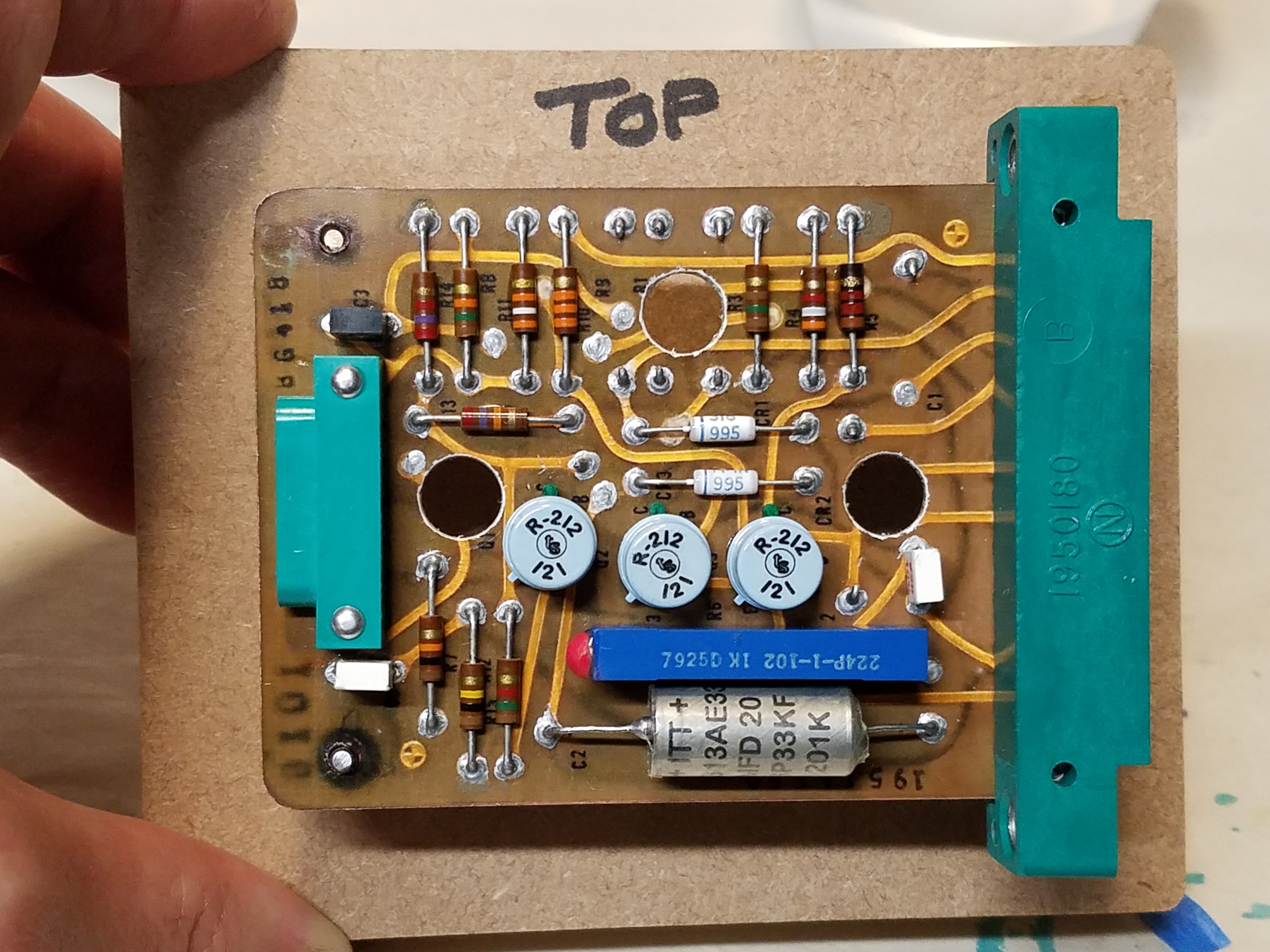
A detail I pointed out in my other article is that the original board is sprayed all over (except for the large connector) with a clear epoxy, or lacquer or some like that. So, I definitely wanted to do the same, plus this would also work in my favor by coating and protecting the photo layer and the edges. I taped off the large connector and used the same clear gloss that I used on the other project. Now the board is done! And it looks pretty real. 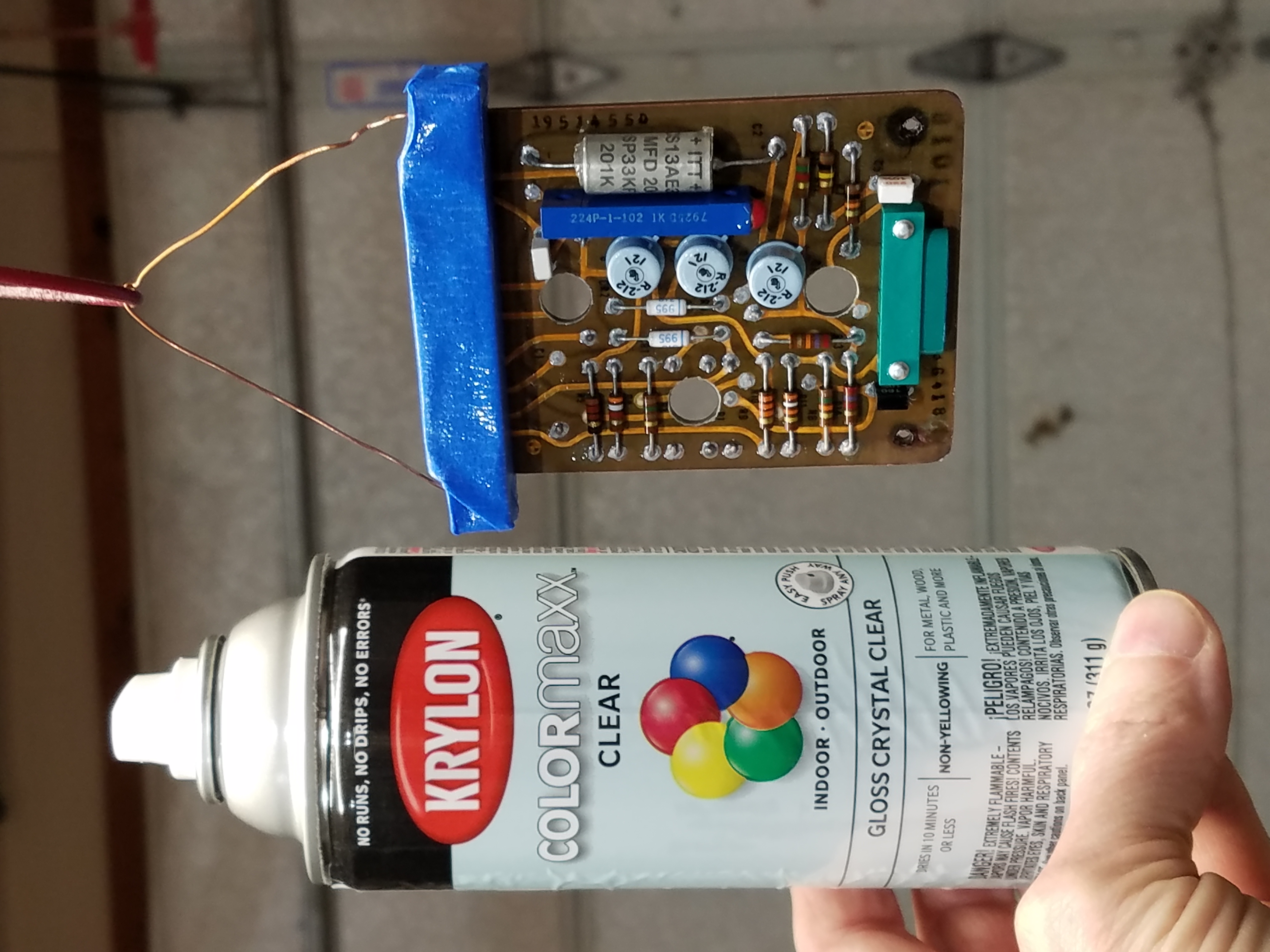
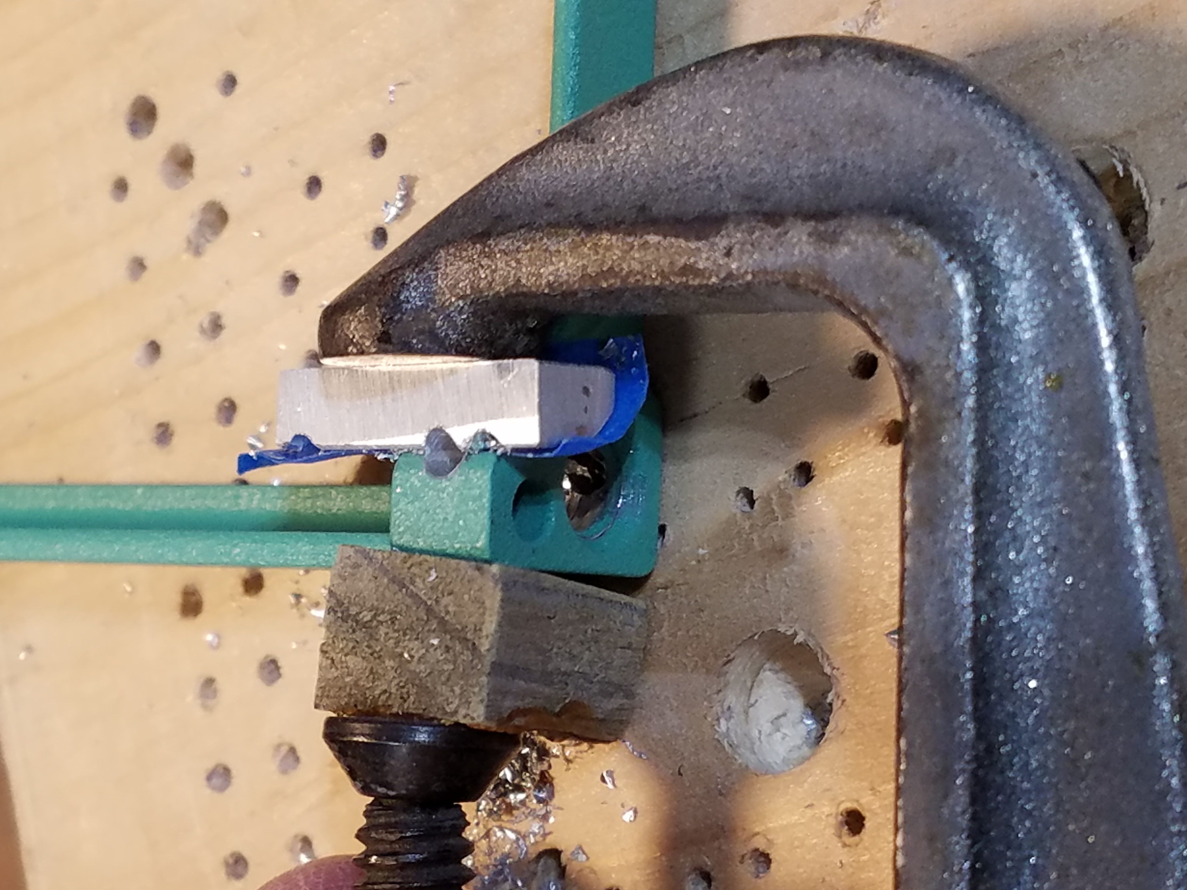
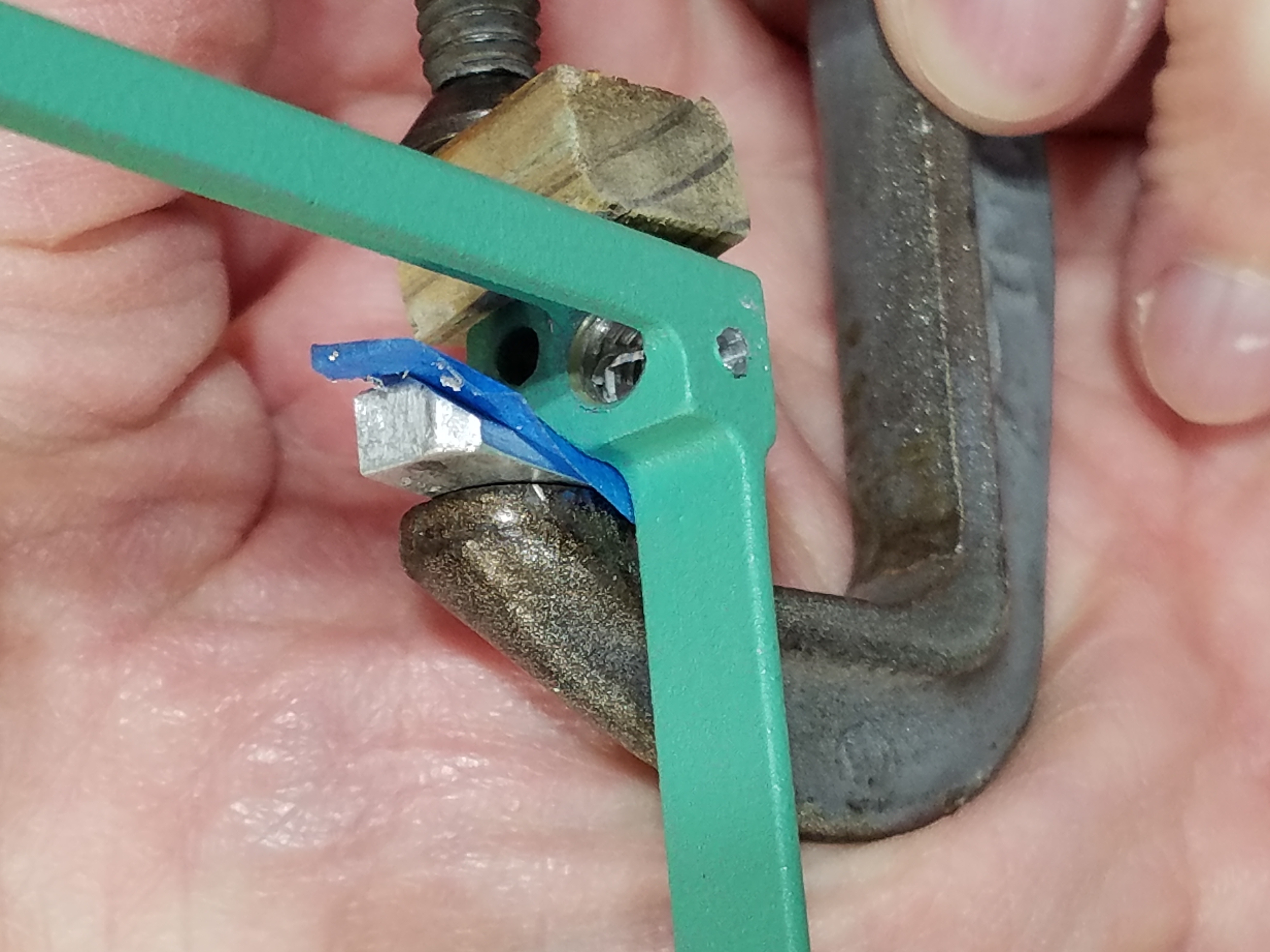
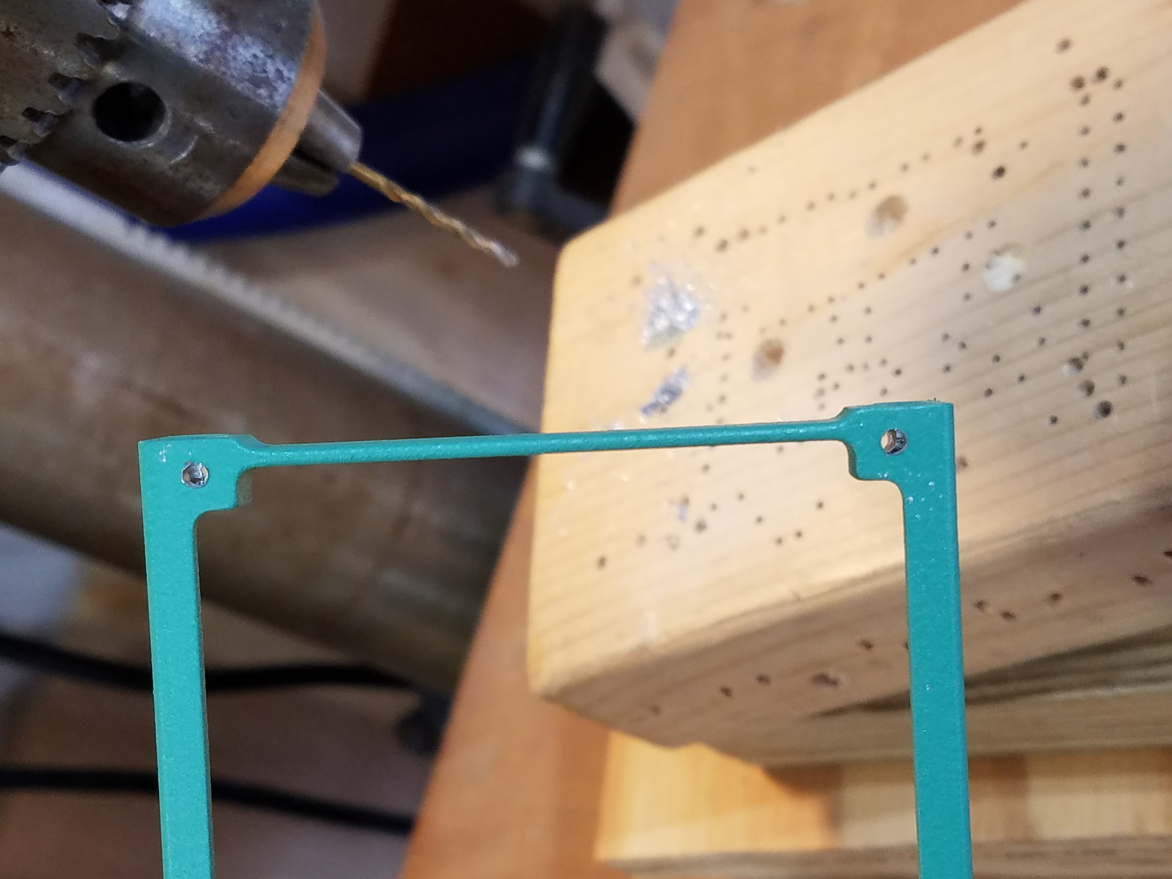
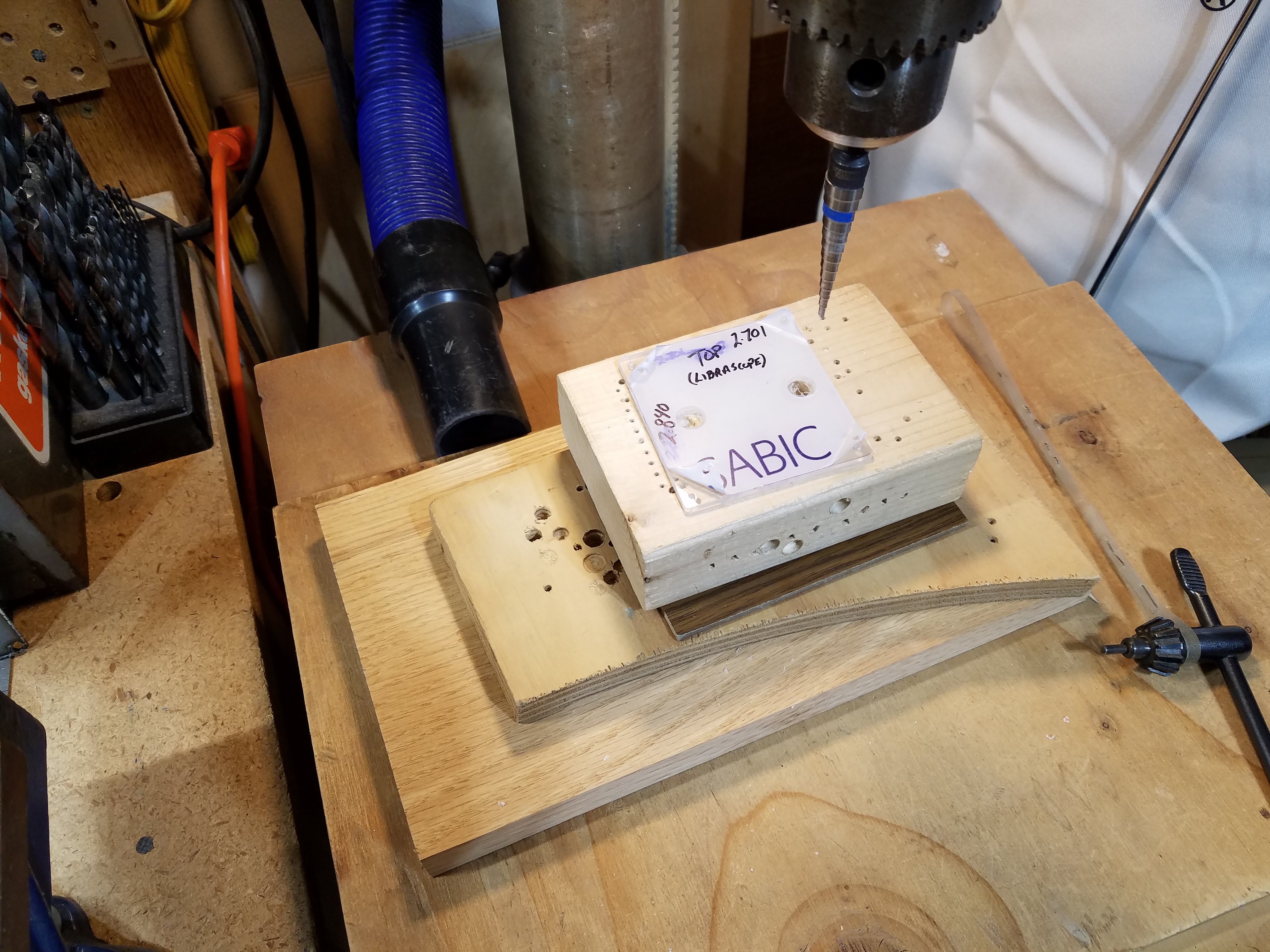
Now onto the frame... I will be using my real NOS Librascope frame. Luckily, I learned A LOT (the hard way!) from my Librascope restoration work and I hoped this would go better than that disaster. Basically, I needed to drill the 4 holes (all the way through) that hold on the clear plastic cover. It sounds so simple, but this was a source of agony on the other project. 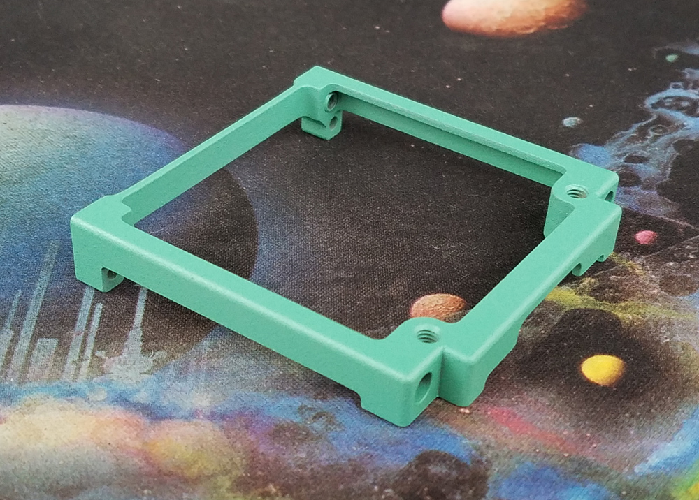
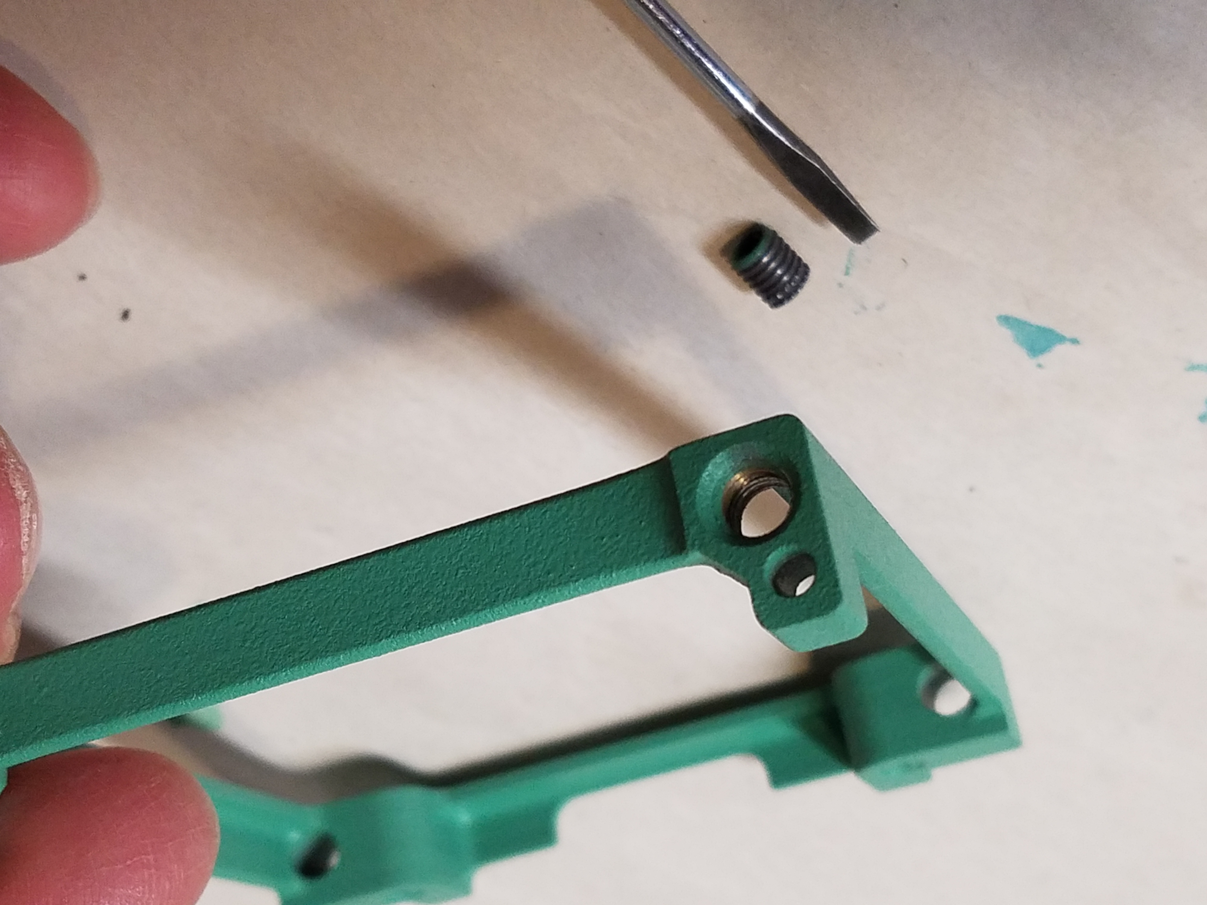
The biggest problem was the hardened steel inserts which absolutely must come out to be able to drill the two holes closest to the large connector. When I did this on the real Librascope one, I had assumed these were pressed in, so I choose to drill them out. What I discovered was the inserts were actually screw-in. Having thought about this quite a bit after the fact, I simply took a 4-40 flat head screw, and screwed it in from the end until it bottomed out on the insert. Then with very little force, I kept turning it until it broke free and the insert started to come out the back side. I finished it by using a small screwdriver and just screwed it the rest of the way out. 30 seconds, tops. OMG! How easy! Arg! If I had only known then... OK, Inserts removed! 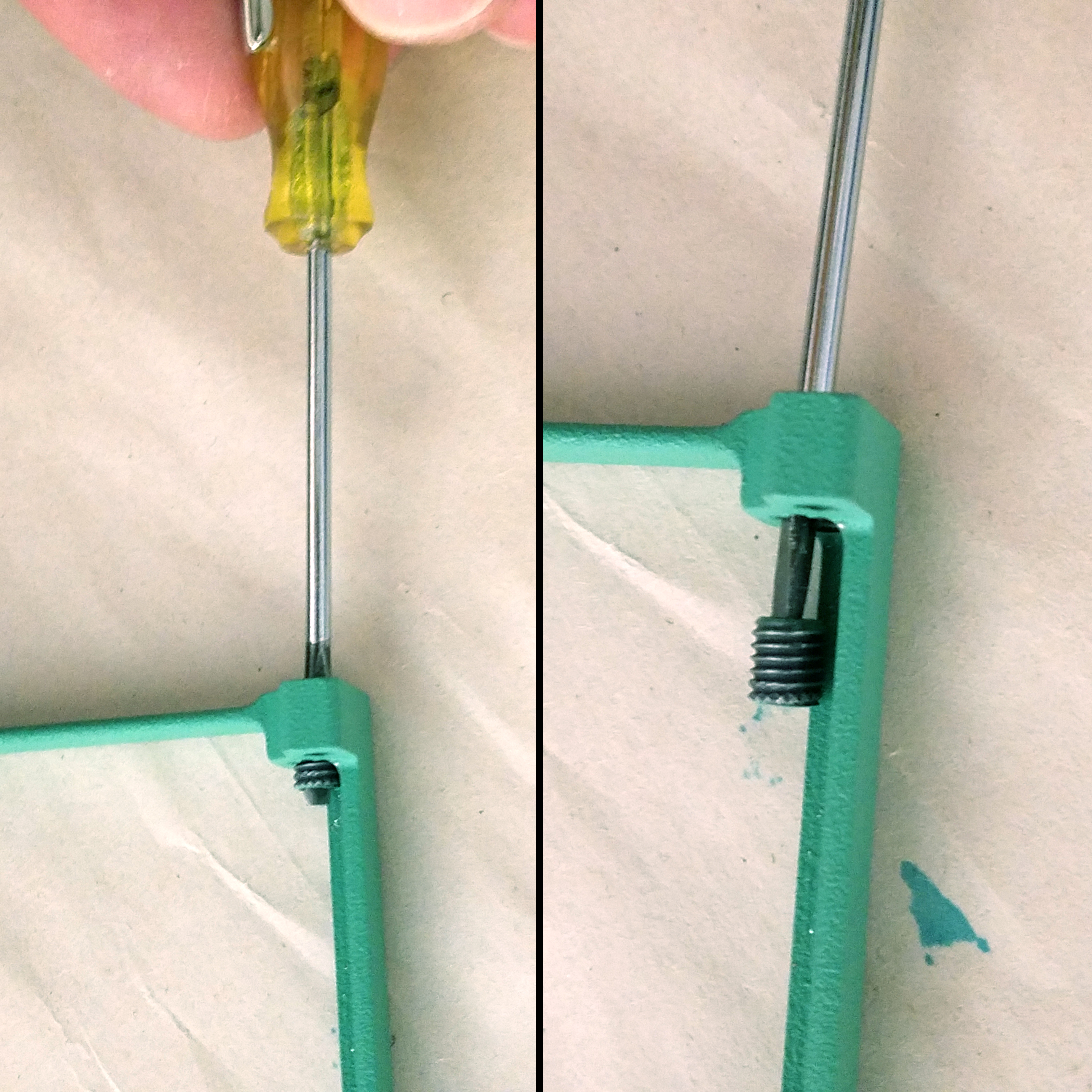
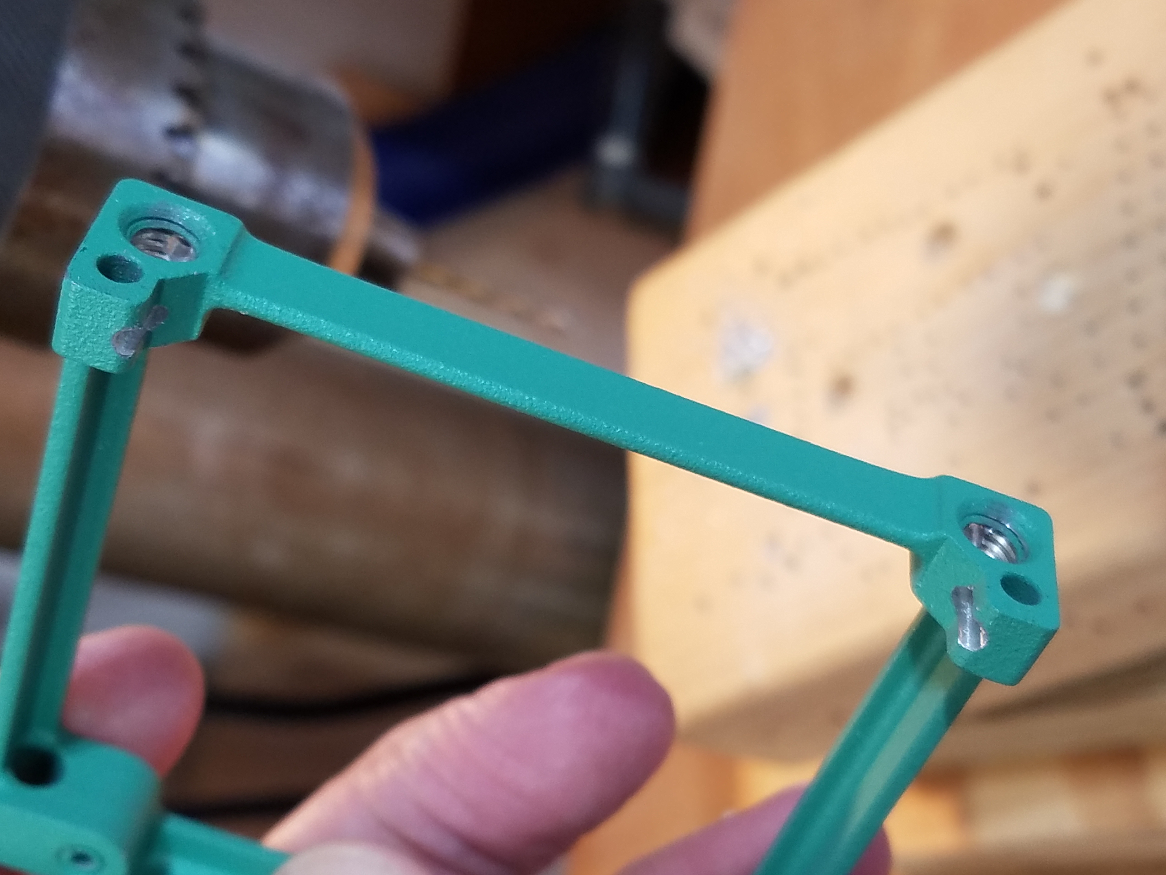
To drill the holes, I used the same technique as with the real one. I backed the "leg" with that little carefully cut piece of aluminum (which I still had) and drilled the holes to bisect the legs and then all the way through to the front. Perfect! Easy! The other two holes are fairly straight forward... and now the holes are done!
Finally, after cutting out another 3/32" Polycarbonate clear cover, I assembled the whole thing, again using authentic screws and nuts I had left over from the restoration. I must say I am pretty pleased with the results. The photos and faux solder techniques worked really well. I do wish I had tweaked the color of the gold leads to be a bit more yellow to really look more gold, but in reality, you won't see it side-by- side with a real one. All in all, I am very happy with how it turned out. Some astute observers my notice that I included 2 components that are not on my Real Librascope Power Pack. I added them because: a) I had them, b) my plug placement didn't require that they be omitted, and c) I can always cut them out later if I want to be more authentic!
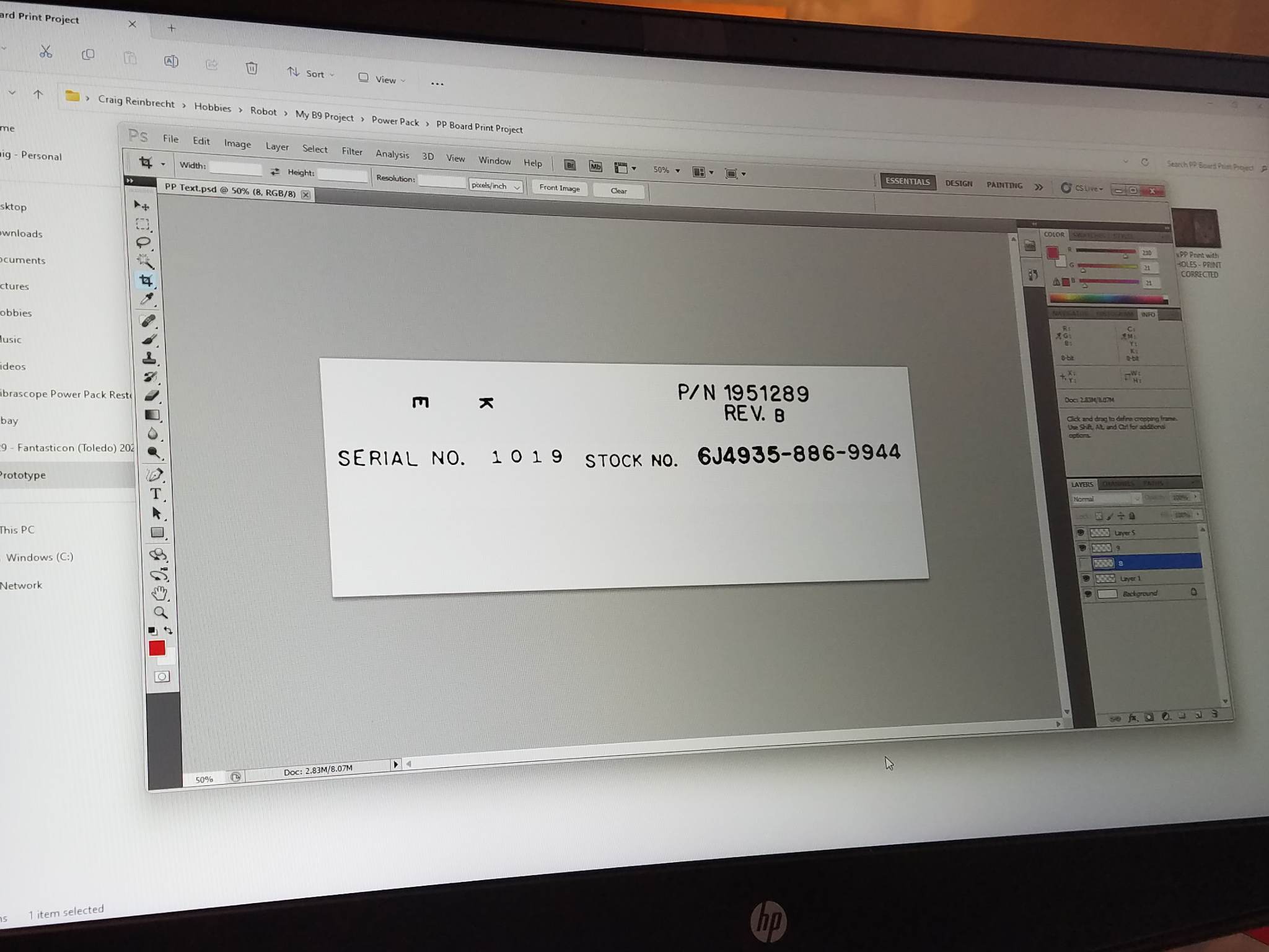
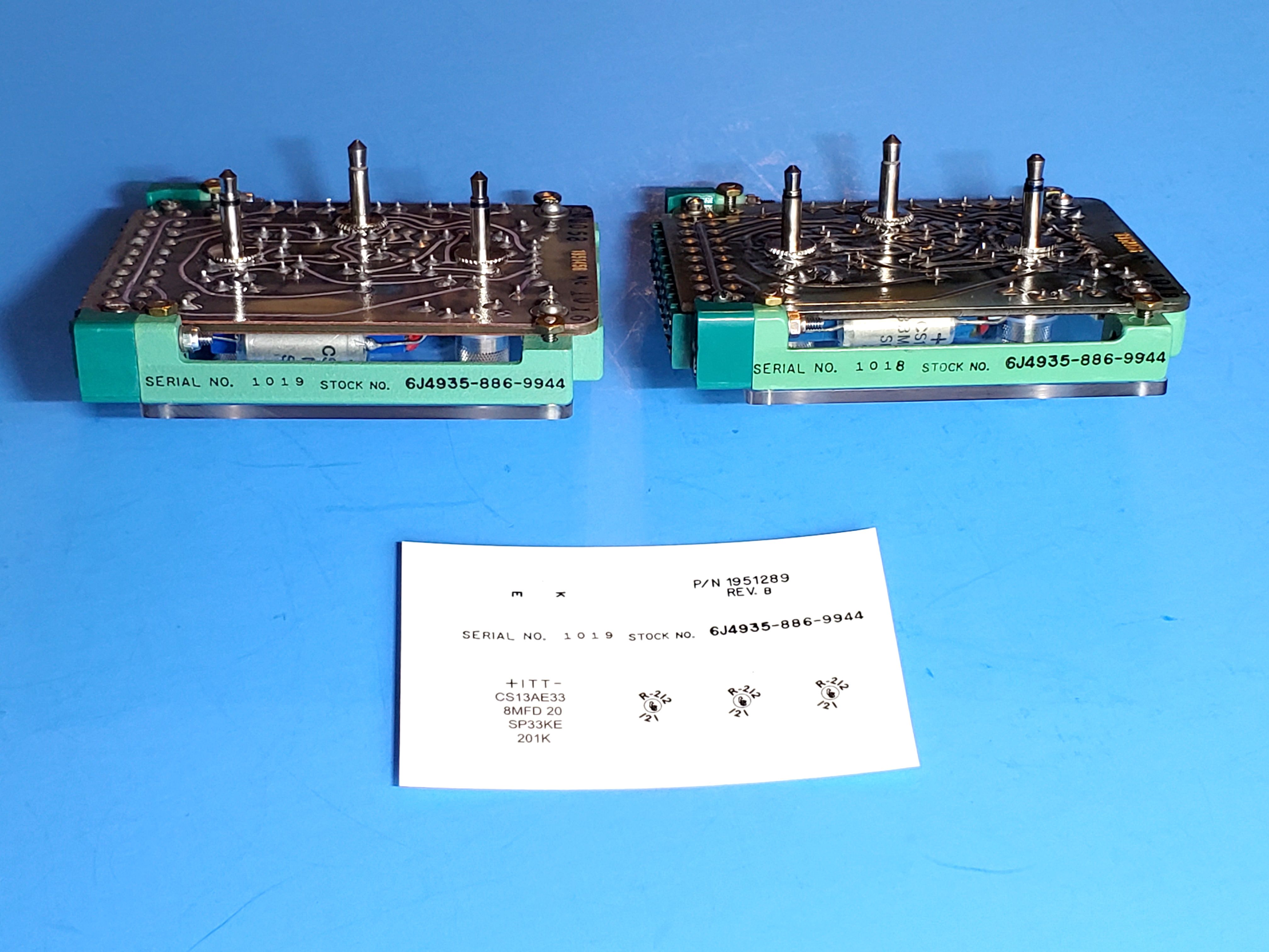
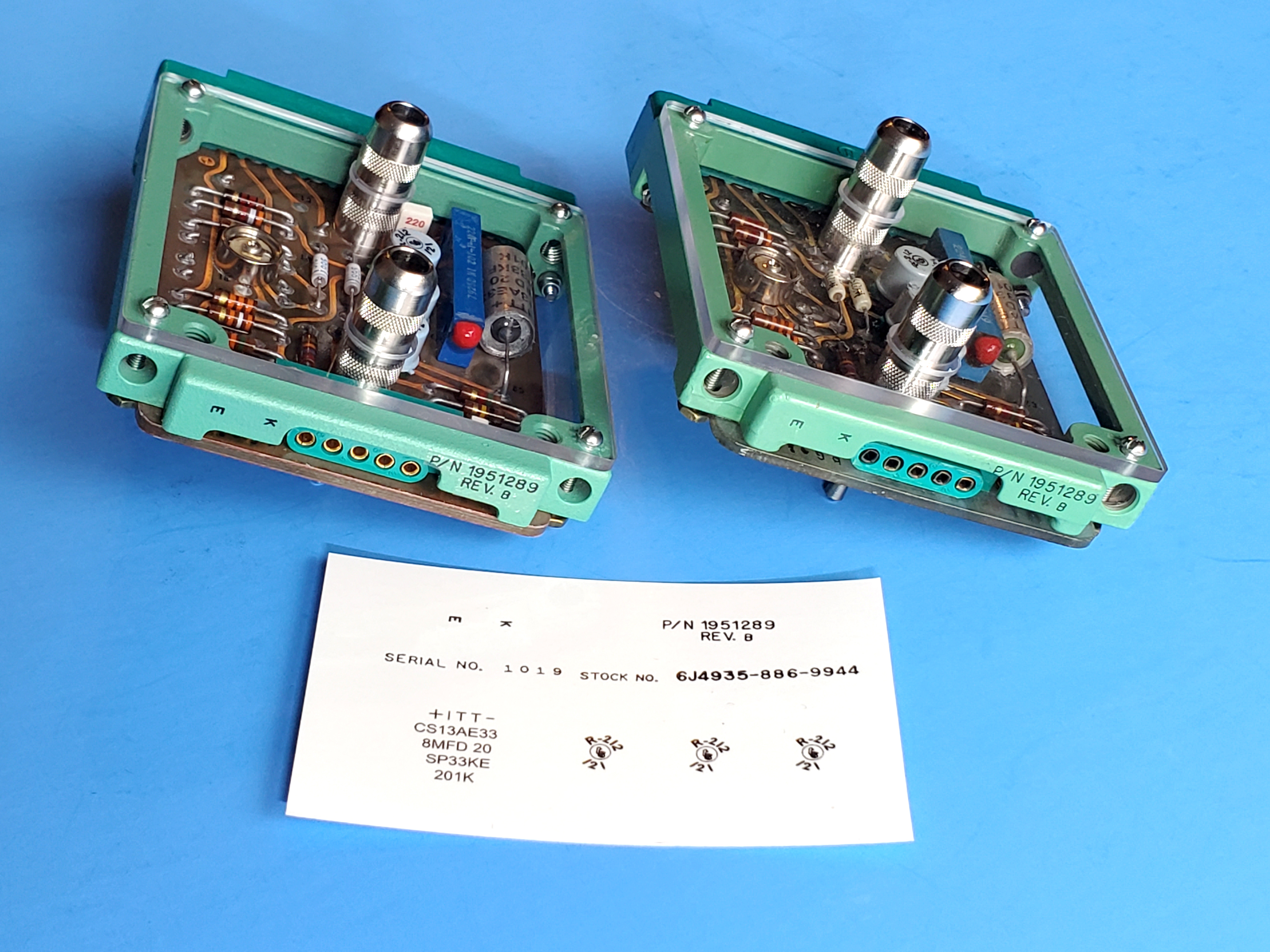
At this point I was going to consider it done, but I decided to go ahead and add one more important detail... water slide decals for the text (serial & part number, etc.) for the sides of the frame, but I had never done that before so I was entering more uncharted territory. I started by scanning the sides of my real Librascope Power Pack, then in Photoshop I assembled a "package" of graphics for the frame and a couple of the components that could also be useful for other B9 Builders. Then I sent them to be laser printed. This was my first attempt at creating Water Slide decals, and I must say, I am blown away at how well they came out and applied. It literally only took about 10 minutes to apply the graphics to the sides of the frame. So, which is the real one, and which is the replica???
This was a tedious project and I don't think I could do this again, but it is always fun to come up with an idea, as crazy as it my seem, and see it through. For all practical purposes I consider it done! Stay tuned!
|
|||
 The Story of One Man's Journy to Build the Perfict Power Pack