


 |
|


| The Builders->Member Projects: Scrap Books->Darrell T | |||
Sensors & Controllers for motorized tread sections
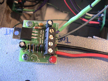
5v voltage regulator for running the control boards. It came as a kit. Very easy to put together and works great.
Two of the four batteries I'll be using. I'l have a 24v system for motors, and two 12v systems for audio and everything else.
Here's a another shot of under the knee plate. You only notice the antennas if you get down low...or if you're a very, very, short person.
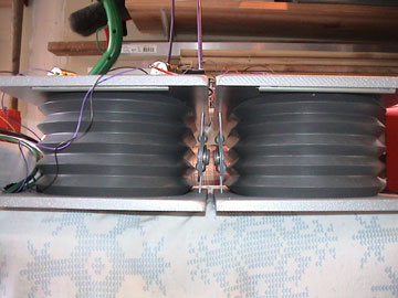
Here you can see inside the knees. There's a sensor board for each of the four antennas. An antenna is mounted on the front and back of each knee plate.
I'm using the Thereminvision sensor system of object avoidance. The technology is old and based on the Theremin sound machine used in old scifi films like Forbidden Planet. It uses capacitance to detect objects. Each of the four antenna senses an object base on density and compares what it finds to the other three. The program will use this info and tell the bot which way to go. This pic shows my knees ready to test the sensors. I'm using 12v motors for the testing.
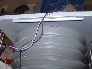
Here you can see the antennas. Any rod will work as long as it's securely fixed in place. I used brass. Positioning them horizontally works will for two reasons. One, it fits the B9's design better, and two, it will work well to keep our pal from doing a header down stairs. I'm not sure how well it will work for avoiding overhanging objects above the waist.
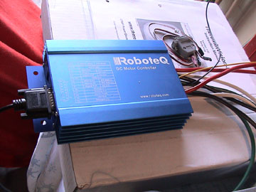
I'm using the Roboteq motor controller for treadsection. There are cheaper ways to go but this has some nice safety and diagnostic features that may be handy. It will be interesting to see how this will work with the OOpic.
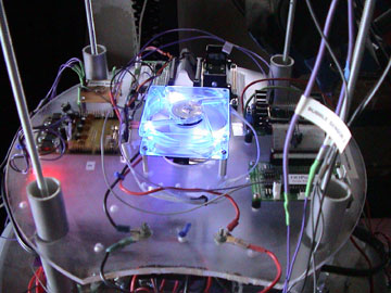
Okay, this has nothing to do with the drive system. This is one of the fans I'm using for cooling and keeping air moving. My bot will glow blue and show through the back vent. I've got very opac acetate covering the inside of the back vent. It looks black if the bot is powered down. You can also see the OOpics that run the arms, bubble, and radar. On the left is a 12v and 5v power board and a small board I made that limits the switches on the arm assemblies.
Another view of the WCM. The OOpic-R has a serial port which is needed for the Roboteq. I don't have a pic here of the wireless handheld controller but will in future posts. It's about the size of a deck of cards and has three modes. I'll use one mode for the autonomous program, one for the R/C program, and one for a future program.
Here's my antenna for the WCM/WHC. It will be mounted between the legs. You'll hardly notice it but it will give me greater range and a clear signal. (I hope)
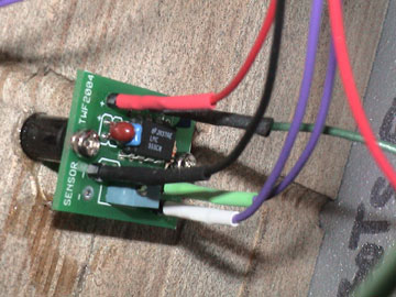
A close up of one of the four sensor boards. Notice the trim pot for tuning the antenna signal.
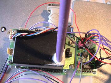
This is only partially complete. I'm using the OOpic-R with
Totalrobots wireless communication module. (the
black box on top) This
way I can have an autonomous robot, and an R/C like over-ride.
It's not like I can pick up my buddy and move him if he gets tangled
in a chair so I wanted to control his movement if need be. The
board on the right is the Thereminvision board. The acrylic
base will also have the voltage regulator and a third small board
for the PAKVII chip needed to translate signal from Theremin to
OOpic. The WCM came with a small whip antenna which I swapped
out for a coax. |
|||
 Darrell
T . ( B9-0028 )
Darrell
T . ( B9-0028 )