


 |
|


| Robot Reference->Construction Tips->Programming Unit | |||
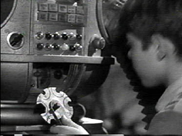
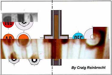
By Craig Reinbrecht These diagrams of the programming panel were developed using some of the best photographs available of the original robot's panel. It is not based on any other available diagrams, only the photographic evidence.
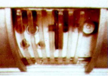
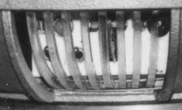
Transferring to a diagram: Once the scale was determined, it was just a matter of printing all the photos to full scale. With the 5 best photos printed, a light box was used to transfer the details to onediagram. It was surprising how all the photos agreed, and the only thing that varied a little was the round thing on the right hand side. This thing definitely has depth, and appears higher or lower depending on the up/down angle of the particular photo. Top and right side: Some assumptions were made on the height and the width of the panel because the top and right side are not visible in any photos. Howvever, you can see the right side in this screen grab:
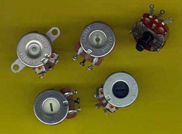
The top and left side in the diagram are based on a logical assumption of proportional dimensions, and this screen grab. Tape reel hole: From the screen grab above, you can clearly see that the tape reel hole appears to be a little smaller than the tape itself (up/down dimension). This is the reason for the side view detail in the diagram. A standard fuse holder would keep the reel hub away from the panel about 1/4". From the diagram you can see that to have a fraction of an inch clearance, the hole would have to be about the same size as the tape (3"). I believe the hole WAS actually smaller than the reel, and this can be seen in several photos including the screen grab noted above. Most likely the tape reel was jammed against the top and bottom opening of the hole, and the tape could not move freely. But why would it need too? I choose to vary slightly from the original in this area. I believe most people would like that fraction of an inch clearance so the tape is not jammed against the hole. If you want your panel to be EXACTLY like the original, the hole should probably be about 2 7/8" high (still centered) making the panel section above and below the hole 9/16". The width dimension came directly from the photos. Round thing: The round thing on the right hand side appears to be a standard round "can" used in many pots, and switches (about 7/8" in diameter). These are very common and exactly the right size and depth. However, I have not seen one with a dimple in the center the same size as the real one. If this was a switch for Bob May, where are the wires? Out of sight in the upper right corner, perhaps?
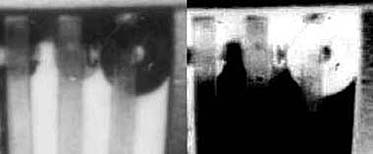
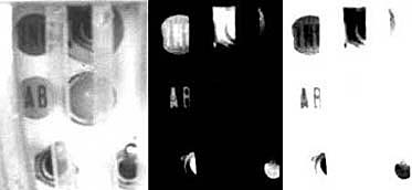
Washer: The thing in the upper left looks pretty clearly like another switch in the best photo, and the washer measures at exactly 1". Maybe there was a different component there, initially, but was replaced by a switch using the washer to hide a larger hole. Panel not centered: It is evident in all the photos that the panel was not centered in the vent hole opening. It is slightly toward the right, and the left edge of the panel can be seen in almost all the photos. Because the door was opened to the right, they may have cheated the panel toward the right to make the switches more accessible. Maybe it was just sloppy workmanship. Color: Probably white, off-white, or a brighter shade of silver than the torso. The one good color photo I have makes it look white. Round labels: I have been told that these were plastic indicator lenses that snapped into a hole. They were never back lit as far as I can tell. I agree with Michael Davis that the middle letter between DC is in fact an E. In one photo if you look closely you can just see the ends of the top and bottom bars from the E. Vince Roberts did some excellent photographic enhancement to the following photo which makes the two right tips of the E stand out. The AB is seen clearly in several photos, but the letter after the IN is not. Michael Davis was told this was a D (IND), and again with very clever photo enhancement we can see that is probably correct. The colors of the labels are very hard to determine. Based on a good color picture, the AB label looks orange. The other two are not obvious, however the IND label is a darker color, I chose red because it has the same look as the photo above when seen in B&W. The DEC is a lighter color based on the contrast in the B&W photos.
Light: The same kind as the 12 belly lights, and it looks amber in the color photo.
|
|||
 Programming
Unit
Programming
Unit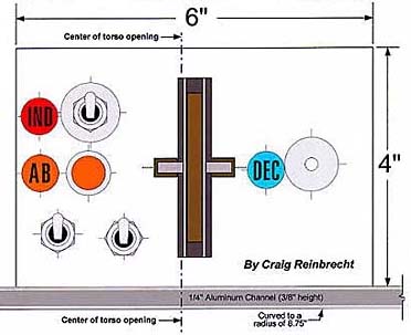
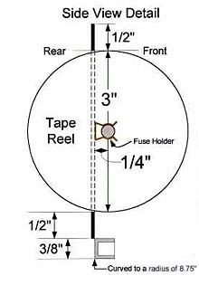 Finding
The Scale: The key to getting this layout accurate was finding
the correct scale. Using the torso vent opening in photos to find
the scale will lead to an panel that is too small, because the panel
sits a good 4" + back from the top of the opening. For this diagram
the tape reel itself was used to find the correct scale. It is a
known diameter of 3" and the tape hub and bottom of the reel are
clearly visible in some good photos. I did consider that the tape
reel might be 2 1/2" but this made the scale of the panel way too
small.
Finding
The Scale: The key to getting this layout accurate was finding
the correct scale. Using the torso vent opening in photos to find
the scale will lead to an panel that is too small, because the panel
sits a good 4" + back from the top of the opening. For this diagram
the tape reel itself was used to find the correct scale. It is a
known diameter of 3" and the tape hub and bottom of the reel are
clearly visible in some good photos. I did consider that the tape
reel might be 2 1/2" but this made the scale of the panel way too
small.