 Homemade
Torso #2 Homemade
Torso #2
By
Mike Joyce
I plan
to construct a mold from which I can produce accurate one piece
fiberglass torsos. Let me start by saying that this is a difficult
project that might be better left to the professionals. Fiberglass
is hazardous and precautions must be taken to ensure fire and health
hazards are avoided.
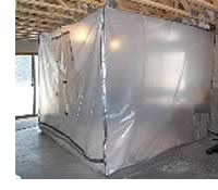 I
made a paint & fiberglass booth to work in, note the fan in
the bottom right corner, air comes into the basement through an
open window, is forced into the booth by the fan and then goes outside
through a window inside the booth. The booth is 10'x10'. I
made a paint & fiberglass booth to work in, note the fan in
the bottom right corner, air comes into the basement through an
open window, is forced into the booth by the fan and then goes outside
through a window inside the booth. The booth is 10'x10'.
After
hearing about long term problems of cracking, etc. with torsos constructed
of wood, bondo and other materials I decided I would attempt to
first create an accurate torso using wood, fiberglass & bondo
and then use this torso to construct a fiberglass mold to allow
production of one piece fiberglass torsos (the ultimate goal).
Construction
of the main torso or "plug" from which the mold will be
constructed
The
torso plug will be constructed from three main parts:
- The
Conical tube
- The
Top Dome
- The
Bottom Dome
These
three parts are separated by two .75" thick rings.
I decided
to create three temporary female molds to allow production of the
male fiberglass part. The three fiberglass sections will be
connected together by two .75" plywood rings.
The Tube
I cut a piece of sheet metal such that, when curled up it forms
a conical tube of the correct dimensions.
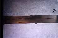
| Picture
of sheet metal before it is cut out. |
|
| Picture
of sheet metal after it's cut |
|
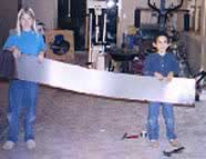
| Frame
to hold the sheet metal. |
|
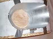
Finished
female tube mold,
ready for fiberglass. |
|
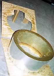
| Removing
the mold from
the fiberglass. |
|
|
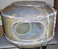
Tube
with arm holes & chest
panel cuts, with rings |
|
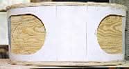
| Another
shot of the tube section, arm sockets and chest panel
trim still to come |
|
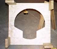
The
Top Dome
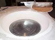
I make a form from waste sheet rock and plaster. A sheet metal
profile of the dome is cut and attached so that it can rotate in
the form to shape the wet plaster to the correct contour.
| A
picture of the dome profile and rotating assembly |
|
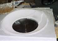
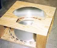
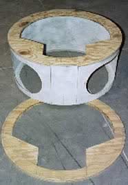
| Here's
a shot of the female mold for the top dome section |
|
| Here
it is after the fiberglass has been laid |
|
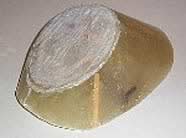
| Here's
a shot of the raw top section |
|
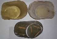
The
Bottom Dome
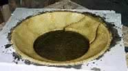
I made another form and created a new profile template to shape
the female mold for the bottom section.
| Here's
the bottom section mold, no trim details yet |
|
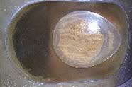
| Another
shot of the bottom section |
|
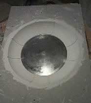
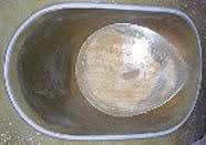
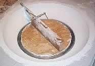
| Trim
added, ready for fiberglass |
|
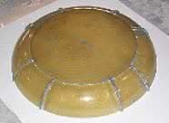
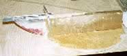
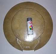
| Here's
the raw completed bottom dome |
|
I decided
to paint the bottom mold with a spray gloss enamel to help with
the mold release. On the top one I just greased it up with
vasoline and the plaster still stuck to the fiberglass in some places.
Of course it doesn't matter that much as the plaster mold is only
used once, but it was messy.
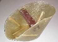
The Arm Sockets
The arm sockets are really difficult! Here's how I plan to
do it. First cut out the hole in the tube section, then user
paper to form the shape of the sides of the socket. Use this
paper template to cut a piece of sheet metal the same size.
Use the sheet metal to form a mold. Fiberglass this mold and
remove it. Use this (inverse) mold as a master to create two
fiberglass sockets. Install them in the holes and add trim.
Simple eh?!
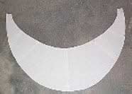
| Here's
a shot of the paper template I made |
|
| Here's
the sheet metal mold ready to create the inverse fiberglass
mold |
|
| Here's
the inverse mold: I will use it twice to make
two arm sockets |
|
| Another
shot of the inverse mold |
|
| Here's
the two raw fiberglass sockets with the mold |
|
| Here's
an close up shot of one of the new sockets |
|
 |
| Here's
the socket with the Bondo trim added |
|
Adding
The Bondo Trim
I used Dave Painter's technique of using foam insulation strips
to make the "forms" for the chest area trim. I then
filled the forms with bondo and let cure. After it sets up,
remove the foam and sand the trim to shape. Remember, since
this must be pulled from a mold there will be some "draft",
in other words the trim is wider at the base than at the crown.
The original was like this also.
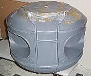
The Pieces Start Coming Together
Here's the plug with a final coat of Duratec sandable fiberglass
primer. (If the primer looks a little rough, it is.
I brush it on fairly heavy to make sure any pinholes, depressions,
etc are filled. When I'm done sanding most of the primer will
have been removed.)
|
|
| Another
shot of the primered torso plug |
|
Note
that I've also added the knob and microphone backplates. Based
on pictures from Michael Davis and my own research using photos
and video, I finally decided not to go with the standard flat raised
circle. Instead I think I've come close to duplicating how
it really was. The knob has a ring with a slight depression,
the microphone's depression is more pronounced.
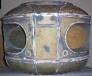
The Ugly Plugling
|
|
| Another
shot of the finished plug |
|
It
has been sanded smooth using a multi step process. 80, 120,
220, 320, 400, 600, 1000 and finally 1200 grit sandpaper was used
to achieve a glossy smooth finish. The different colors are
green for fiberglass, pink for Bondo, white for glazing compond
(to fill small holes) and grey for the Duratec catalyzed primer.
Weird looking, eh!?
12/30/99
That's it for the plug. About 70 hours, and around $500 dollars
later it's done. Next I will make a mold from this plug.
This plug could be used for a replica as is, once the holes were
cut. But I'm not sure that the wood & bondo would hold
up over time without cracks. Thanks for the support!
|