


 |
|


| Parts Store ->Vendors->B9 Foundations->Soil Sampler | |||
Questions? Email dschulpius@gmail.com The Mike J Functional Soil Sampler B9 Foundations is proud to present the "Mike J Functional Soil Sampler". This animated Soil Sampler adjusts to fit most Tread Sections and arrives fully assembled. Be sure to read the online manual below to fully understand what is included and what will be required for you to install it in your Robot. (A printed version of the manual is included in your purchase) Click here for a short Windows Media demo video of the Soil Sampler in action! SoilSampler.wmv (1.1 MB) Be sure to read this entire page before placing an order! Online
Owners Manual:
Click Here For PDF Manual File
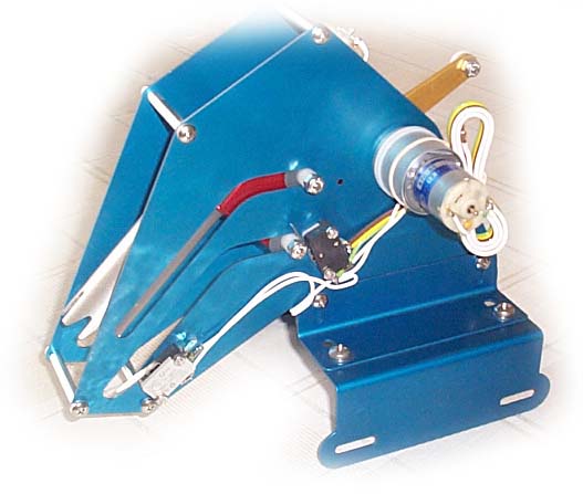
Overview The Mike J Functional Soil Sampler(FSS) is a precision made unit designed to duplicate the animated soil sampler used by the Robot in the first season episode, Island in the Sky. In this episode the Robot exits the Jupiter II with instructions to analyze the alien planets environment. As the camera focuses upon the right tread section of the Robot we see a small door slowly open and watch as a drill tube extends out. As the tube nears the soil it begins to spin, drilling into the alien planet. After taking the sample, the drill tube stops spinning, retracts into the tread section and the cover closes. Now, with the Mike J FSS, you can replicate that exciting scene with just the flip of a switch! The FSS is designed to mount inside the right treadsection and requires only the hookup of a 12 volt power supply and connection to an activation switch (use of one of the three programming bay switches is suggested). The FSS comes fully assembled and is adjustable to allow installation in most tread sections. It has been successfully installed in Norm Sockwell s aluminum tread section, Scott Sanderson s steel tread section as well as in Dana Covert s aluminum treads (no longer available). Installation in other tread sections should be possible but may user require modification of the mounting hardware. See the Installation section for mounting details. The unit is constructed out of precision laser cut parts. The drill tube has been CNC machined out of solid aluminum. All parts have been anodized for a professional finish that will not corrode. Two precision gear motors are used. One motor drives the extension & retraction of the drill tube unit and the other spins the drill tube. The unit is activated by depressing a switch or toggle for a couple of seconds. After this you can step back and observe the entire cycle. No additional sensors or electronics are required, the FSS comes ready to go. As a safety feature, the drill extension connector is designed to pop off if the movement of the unit is obstructed during operation. (This feature is to help avoid accidentally taking a sample of your foot, for example!) Electronic interference from the motors is filtered by a noise reduction capacitor on each motor. This helps minimize electrical interference from the motors which might cause static in the sound system or the neon to flash when the soil sampler is in use. The compact design allows all components to operate below the level of the upper wheel axle bolts. This is important if you wish to use these upper bolts when mounting supports, etc. for the upper legs. Also, the unit is designed to allow a person s foot to fit within the tread section if Robot is constructed as a costume suit. (CraigR s Robot is a costume. He demonstrated the use of the FSS at FV2004, with an operator inside the Robot.)
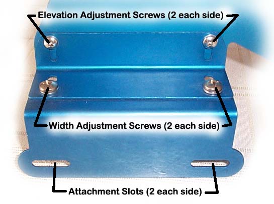
Installation There are several steps to installing the FSS. First it must be physically mounted. Second, testing and adjustment of the mounting position to ensure proper operational clearances is required. And finally, wiring the unit to the power supply and the activation switch finishes the installation process. Take time to read through this entire document before beginning. It is important that you understand how the unit operates and how its mounting position can be adjusted. Failure to properly mount the unit could result in it binding or jamming which may result in damage to the unit. Failure to correctly power the unit may also cause problems. Note that the unit is moved into position through the bottom of the tread section. If your Robot is already assembled, you will have to disassemble it in order to give you full access to the tread section from all sides. The side panel will also need to be removed during the mounting and testing phase. There are three axis through which the unit may be adjusted. First the width of the unit may be changed to allow it to fit snugly between the inner vertical plates. This adjustment is made by loosening the four Width Adjustment Screws. The elevation(or height) of the unit may be adjusted by use of the four Elevation Adjustment Screws. The FSS is attached to the tread via the four Attachment Slots. These slots are designed such that the axle bolts from the wheels extend through the slots and the axle nuts then hold the unit in position. Fore/aft position of the unit is determined as the unit slides fore/aft on the axles that pass through the four Attachment Slots. Use this photo to help identify these items:
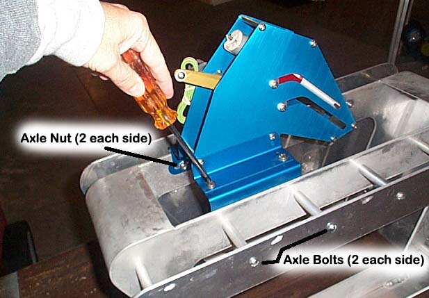
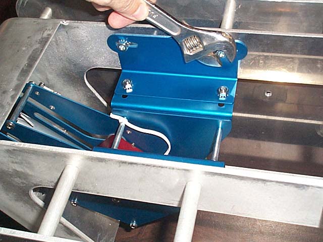
Step 1, Determine and set the correct width adjustment. Turn the tread section upside down. Loosen the four Width Adjustment Screws. Set the FSS into place with the unit sitting up out of the tread section and pointing aft. As shown in this photo:
(You will need to ensure your axles extend far enough into the interior of the tread section that you can put the four slots over the axles and still attach the nuts. If your axle bolts are not long enough you will need longer ones. Axle bolts and nuts are not provided.) Secure the unit in place with the axle nuts. Note that you can now slide the upper portion of the FSS from side to side a bit. Make sure the upper portion is centered and then tighten the four Width Adjustment Screws. Remove the axle nuts and back the axles out far enough that you can remove the FSS by sliding it straight up. (See the above photo, hopefully a picture is worth a thousand words!)
Step 2, Mount the unit in position for initial testing. The unit should arrive positioned to the highest elevation position. The elevation can be adjusted(if needed) using the four Elevation Adjustment Screws. Check that the elevation is adjusted to the full up position (the tallest position). With the four wheel axles backed out, slide the unit into position carefully. While holding it in place, insert the axle bolts fully so that they engage the four Attachment Slots. Place the axle nuts on the bolts finger tight. (See the photo below.) This will allow you to easily loosen them and slide the unit fore/aft as needed. To determine the initial fore/aft position, hold the soil sampler door closed. Slide the unit forward until the tube contacts the inside of the soil sampler door. The best position for the unit is as far forward as it can go but note that this position may not allow the soil sample door to open fully. In my experience this is a good thing since opening the door too far can result in the upper edge of the opening scratching the paint on the door where it contacts.
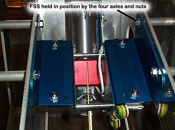
Step 3, Adjusting the final FSS position. During this step we will be using a power supply (12 volts DC) to momentarily apply power in order to slowly step the unit through the extension/retraction cycle. During this process we will be watching carefully to ensure clearance. If needed, the unit must be removed and adjusted (elevation, or fore/aft position) to avoid binding. I suggest using extra long wires running from your power supply to the unit. Note that your wiring harness has four color coded wires; white, brown, yellow & green. For this test we will connect the white wire to our positive voltage (12 volts DC) and both the brown and green wires to ground (GND). The yellow wire is not used. Warning: When you hook the unit up in this manner it WILL RUN CONTINUOUSLY when the power is on! Set up the test so that you can quickly and easily turn the power on & off. This will allow you to apply power in small steps to slowly move the unit through the entire cycle. Continue to tweak the unit s overall position until you can run the entire cycle with satisfactory clearance. Once this final position is determined tighten down all the adjustment screws and axle nuts. Do NOT reverse the polarity of the power supply, the unit will not function correctly in "reverse".
Step 4, Wiring. For final wiring you will need to connect the unit to a fused, 12 volt DC power supply capable of providing at least 1 amp of current. Be sure to use an inline fuse (not provided) to protect your motors in the event the unit becomes jammed. Failure to use a fuse may result in permanent damage to the motor(s) if it s operation becomes obstructed! An inline fuse can be purchased at most electronic supply stores such as Radio Shack. The fuse should be rated for 1 amp. Connect the white wire to your fused, 12 volt power supply. Connect the brown wire to Ground. Run the green & yellow wires up to the programming bay and connect them to a single pole, single throw, normally open switch (SPST N.O.). I suggest using one of the three toggle switches in the programming bay for this function. You can use either a normal toggle switch or a momentary (spring loaded to the N.O. position) toggle switch. In either case, activating the switch for 1-2 seconds (Holding it in the on position then returning it to the off position) will start the drill extension cycle. Once activated the unit will extend, drill and then retract, shutting off automatically. It is left up to you to determine what additional wire, connectors, etc. are best for use in your particular installation.
Operation Once properly installed, activation of the soil sampler is done by simply holding the activation switch in the on position for 1-2 seconds and then returning it to the off position. If the unit is installed properly it will extend slowly, pushing open the soil sampler door as it extends. As the unit nears the last inch of extension the drill bit will start spinning. It will continue to spin until the drill starts retracting. As the unit is pulled back into the stowed position the door should close due to gravity. The unit should not require maintenance or lubrication but should be kept clean. Enjoy! B9 Foundations
Disclaimer: B9 Foundations has done its best to provide an
excellent product. However,
successful installation and use depends greatly upon the skills
and knowledge of the user doing the installation and we can not
be held responsible for any damage or loss due to incorrect installation.
We recommend you contact a reputable electrician if you have
any questions as to the proper wiring, etc.
|
|||
 Functional
Soil Sampler
Functional
Soil Sampler