There are several methods that can be used in forming the B9 bubble. I have known people who try to take a 15 acrylic sphere and try to form the bubble by heating it, and squashing it down, but this method is extremely difficult to accomplish. If the bubble is sitting inverted, with the hole facing up, and is brought to too warm a temperature, it tends to collapse in on its self, resembling a deflating beach ball, or a beached jellyfish. Attempting to rectify this by turning the sphere upright, with the hole down, resulted in a mushroom shape, as the outer perimeter drapes down over the rim around the flange of the hole.
It is better to use a vacuforming box to create a sphere with the hole facing up, take a curved plate the same shape as the top of the B9 bubble, and use it to squish the sphere by bringing it up into the sphere before it cools. However, this method is rather difficult as well, due in part to the fact that the curved plate must remain perfectly level while it is being raised into the sphere, resulting in a misshapen bubble, high on one side and low on the other if not done correctly. Achieving this would require an elaborate set up of platens and guide pins, which would be far more cost prohibitive than its worth!
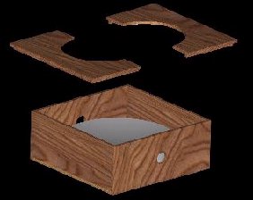
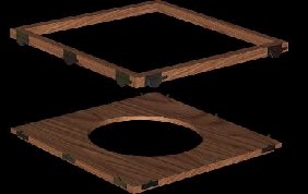
The solution I came up with achieved effective results, after a great deal of trial and error. I built a 20 x 20 x 8-3/16 box. Using a lathe, I machined an 18 round wooden plate, 2 thick with a 34 radius concave surface, and then used four 1-1/2 tall wooden blocks to support the concave dish off the bottom of the box. I cut a 2 hole in the side of the box to accept the Shop-vac hose. Make sure you have at least 5 clearance between the bottom of the curve in the concave dish and the underside of the box lid halves, and no more than 5-½, or your bubble could be mis-proportioned.
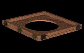
I then had to make a lid, so I made a 20 x 20 x ½ thick lid with a 12 diameter hole in the center, and cut it in half so that when the bubble was formed, the lid could then be disassembled to remove the bubble. If the lid was one piece, the bubble would be captured and the lid would have to be cut off from around it, which could result in damage to the bubble.
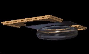
I made a 20 x 20 x1 wide wooden frame with cam style window locks to clamp a 19 x 19 x ¼ piece of clear lexan on top.
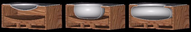
The principle of this fixed concave dish to box ratio is simple. When you try to pull a vacuum on a sheet of soft, hot plastic, by nature it will try to form a perfect sphere, due to equalized low pressure on all sides from within the box. If something were to interfere with only one quadrant of the forming sphere, the rest would continue to form with round edges. If the interfering object were a concave dish, the controlled expansion of the sphere on this surface could be made to blend with the smaller radius at the horizontal perimeter of this squished sphere, forming the robot bubble head.
Now it was time to heat the plastic, which I did. I placed the lexan in the frame, clamped it to the lid, and stuck it in a big industrial oven to heat it to 350 degrees. When it got soft, I removed it from the oven, quickly placed it on top of the box, turned the vacuum on and UH-OH! The bubble expanded so quickly I didnt have time to react and shut off the vacuum. The sphere quickly filled the box and became a cube with a round convex circle on top instead of a bubble.
There were two main problems here. One was controlling the vacuum by just pulling the hose out or turning off the Shop-vac. A very awkward means of vacuum pressure control! The second problem was the fact that I couldnt see how far the plastic was expanding very well just by looking down through the bubble hole. I corrected this problem by removing one of the sides of the box, and replacing it with a sheet of ½ clear lexan, creating a nice, strong window to monitor the bubble expansion. Now, to correct the vacuum control problem, I needed some way to accurately control the size of the expanding bubble.
I constructed a valve using a piece of 1 PVC pipe approximately 6 long. I made a 1-½ x 5 rod out of wood and made a tube out of it by cutting a hole in the center of it the same diameter as the OD of the 1 PVC tube. (About 1-1/8) A wooden plug was glued in one end of the wooden tube to close it off. I then slid the smaller PVC tube into the larger wooden tube til it bottomed out against the plug.
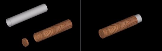
With these assembled together, I drilled two holes, ¾ diameter, along the length of the tubes making sure to pierce both tubes on one side. It resembled a flute, but by twisting the large tube around the small tube, the size of the openings of these ¾ holes could be adjusted to become smaller.
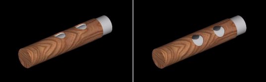
There was about an inch of the smaller tube sticking out of the larger tube, so I drilled a hole in the box large enough to accommodate this extension, and glued it in place. (Just the PVC tubing, NOT the outer wooden tube)

Now my box had a carburetor of sorts, which could be used to control the vacuum pressure inside the box. I tried to form another bubble, and this time was able to open the valve to slow the expansion of the sphere, but I slowed it too much, the plastic cooled quickly and started to shrink like a balloon deflating, and was kind of cloudy. I tried again and got too large a bubble, it was malformed at the edges. Two, then three more times, and I finally got the hang of it, but was quickly running out of plastic. It worked ok as it was, but being the picky person I am, there was something about the control that just wasnt right. The response from adjusting the valve was just too quick, Not enough tweaking time, so a friend suggested I create a baffle to help regulate the vacuum pressure in the vacuform chamber.
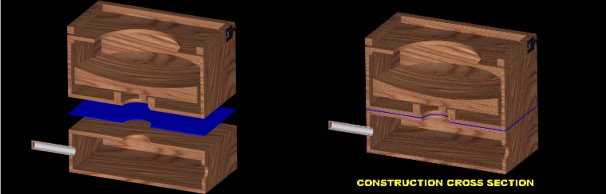
I constructed a 20 x 20 x 6 six sided box with a 4 hole in the top center. I then cut a 4 hole in the bottom center of the bubble forming box, lined the four 1-½ tall dish support blocks around the hole inside the forming box, mounted the dish on top of these so that the vacuum would be pulled from directly below it. I cut a piece of 1/8 rubber sheet 20x 20 with a 4 hole in the center to use as a gasket between the two boxes. I glued the rubber to the top of the baffle box, then glued the whole thing to the bottom of the forming box. I then relocated the valve and the shop-vac holes to the baffle box and plugged the old holes in the forming box.
Now was the moment of truth, to try another bubble. I got some more plastic and set out to destroy more lexan sheeting in my quest for the perfect bubble. The effect of the baffle box had a subtle, subdued effect, but it definitely provided a nice delay when adjusting the valve. I quickly caught on to the valve adjustment, more so than with the forming box only. I only wasted three pieces of lexan before I got it right. The only problem is if you wait a while before doing another, (like a few weeks) you need to go through the learning process of valve control again. I had one piece of lexan left, and it had been three months since my good bubble came out, and I tried to make another. The results were less than favorable.
The one thing to watch out for, If you try to form the bubble too fast, it stretches extremely thin, kind of like a 2-liter pop bottle, so constant valve adjustment is required to get a good, slowly expanding bubble. Just be sure not to go too slow, or the plastic will cool and harden before complete. Its one of those things you have to get JUST RIGHT! A very steep learning curve.
Click here to download Terry's CAD file (dxf format) of his Bubble Box
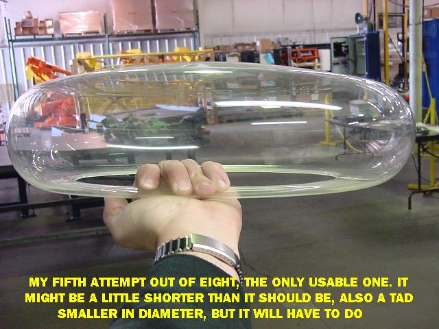
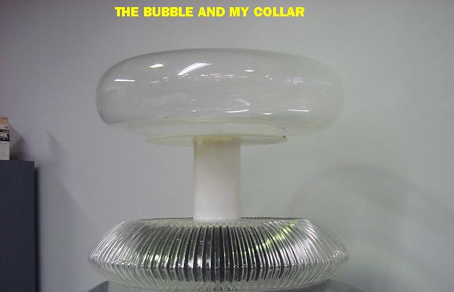
Photos of the finished bubble: