Time is flying and the third annual club meeting is only 34 days away, time to get busy!
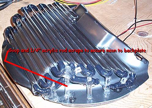
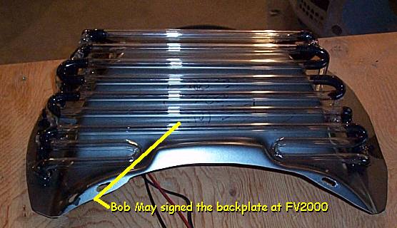
I really wanted
to secure the neon to the neon backplate, but after hearing several horror
stories about broken neon I didn't want to use wires to secure it.
So instead I used some scrap pieces of 1/4" acrylic rod and GOOP glue.
It's messy to work with and the final look doesn't appeal the neatness
freak in me, but it is very secure and after all it won't show.
Here's a couple
of shots:
Neon
photo 1
Neon
photo 2
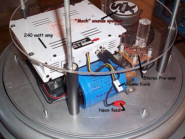
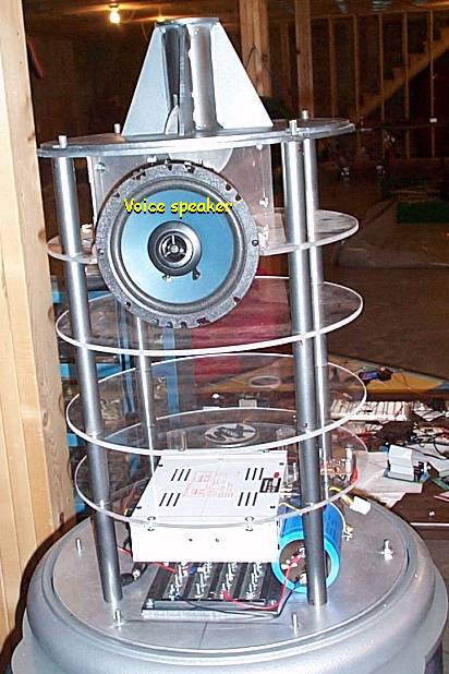
I finished testing
the stereo system. The audio output of my laptop required a small
pre-amp which I built with a couple of LM386 chips from radio shack.
The output of the right channel gets split off after the pre-amp to feed
the neon's audio sync unit. This allows the sync unit to receive
a high level output and achieve good sync even if the volume of the main
amp is turned down. The main amp is a 240 watt car stereo unit with
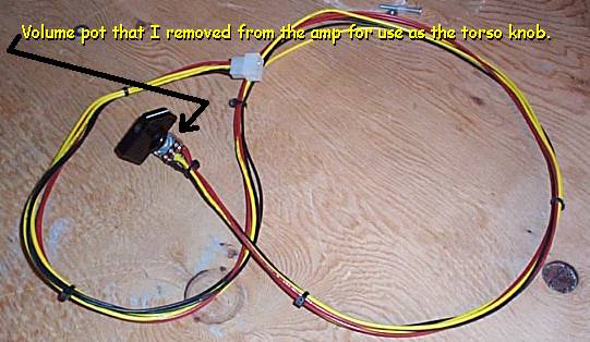
it's own volume control. I removed the volume potentiometer from
the amp case and added an extension to it. This will allow it to
be place in the torso so that the torso knob can directly control the volume.
Here's some shots:
Amp
photo 1
Amp
photo 2
Amp
photo 3
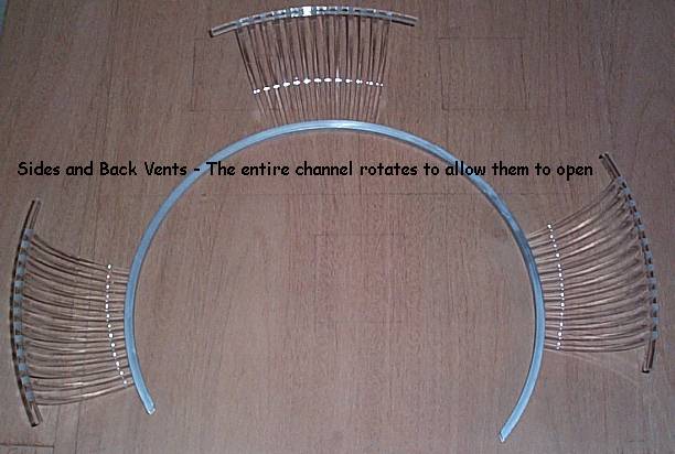
I needed to make
sure my side and back vents opened because I will need access to connect
the torso wiring to the central support structure. Craig made me
a 360 degree channel and I had first planned for the vents to all slide
in it. I soon realized that this would not be practical. Instead
I've cut an approximate 200 degree section of it and will fix the vents
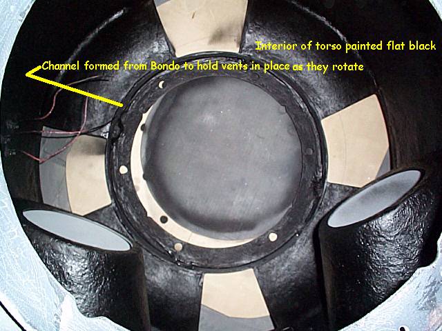
to this channel. After temporarily securing the vent channel in place,
I used bondo to form a guide for it. The channel and three vents
will all rotate just enough to open all three simultaneously.
Here's a couple
of shots:
Vents
and channel:
Inside
of torso with bondo channel guide (hard to see it).