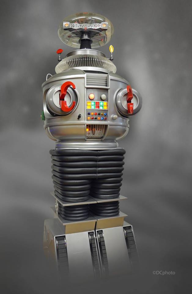
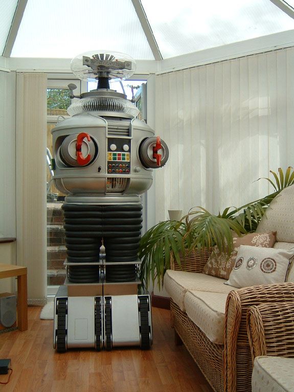
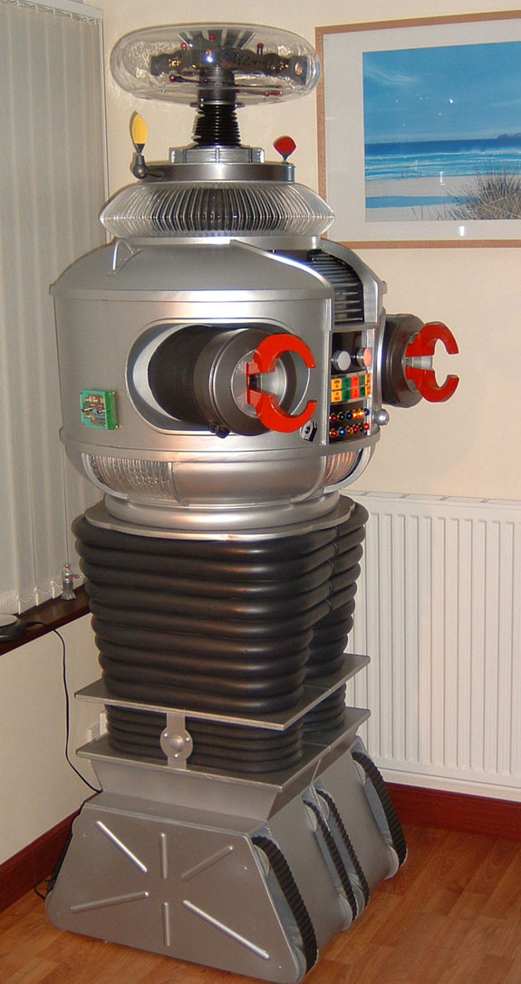
B9 Robot Building Through The Years
Strap in and click below
2017
03/24/2017
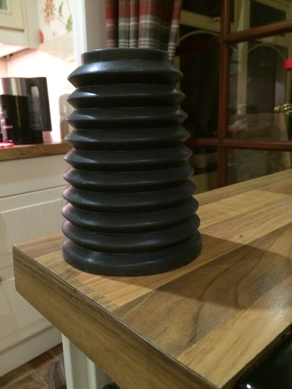
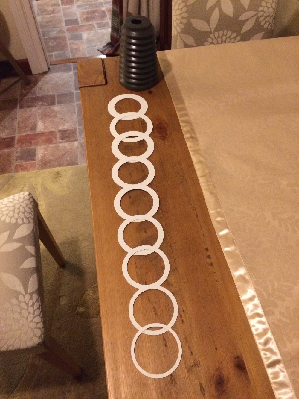
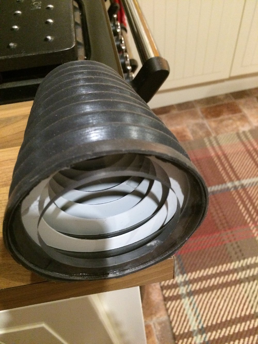
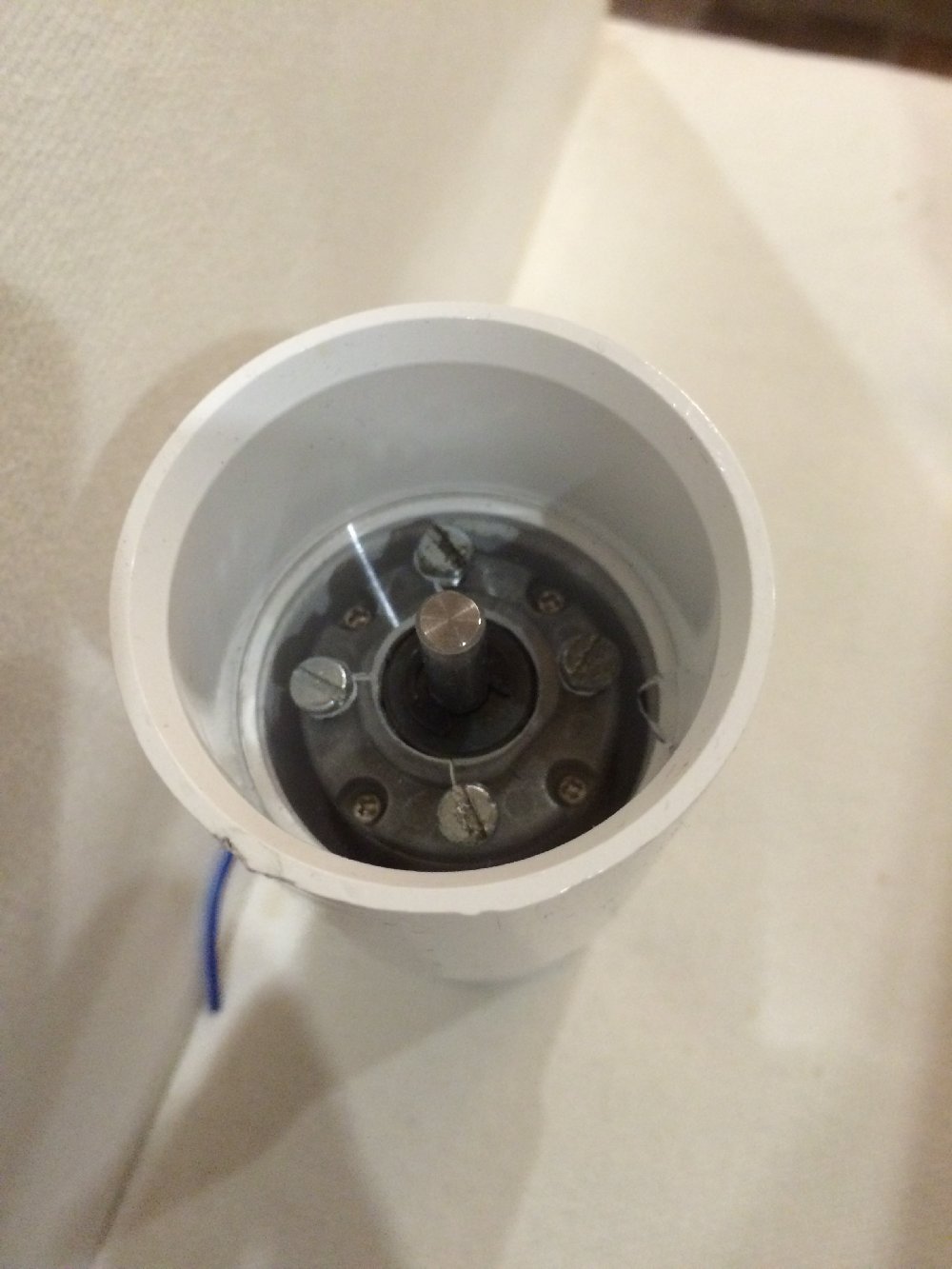
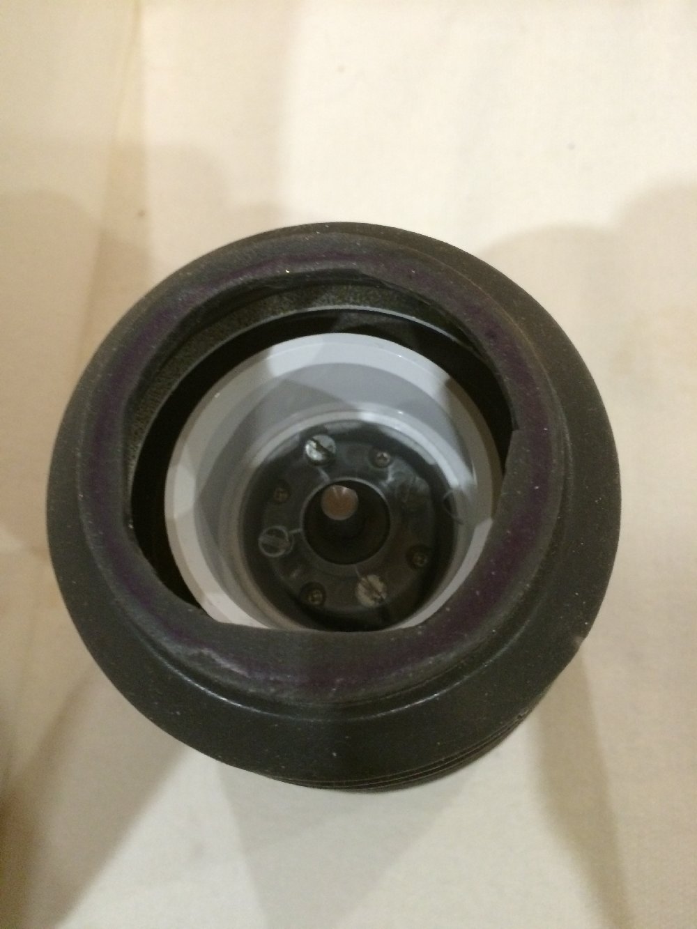
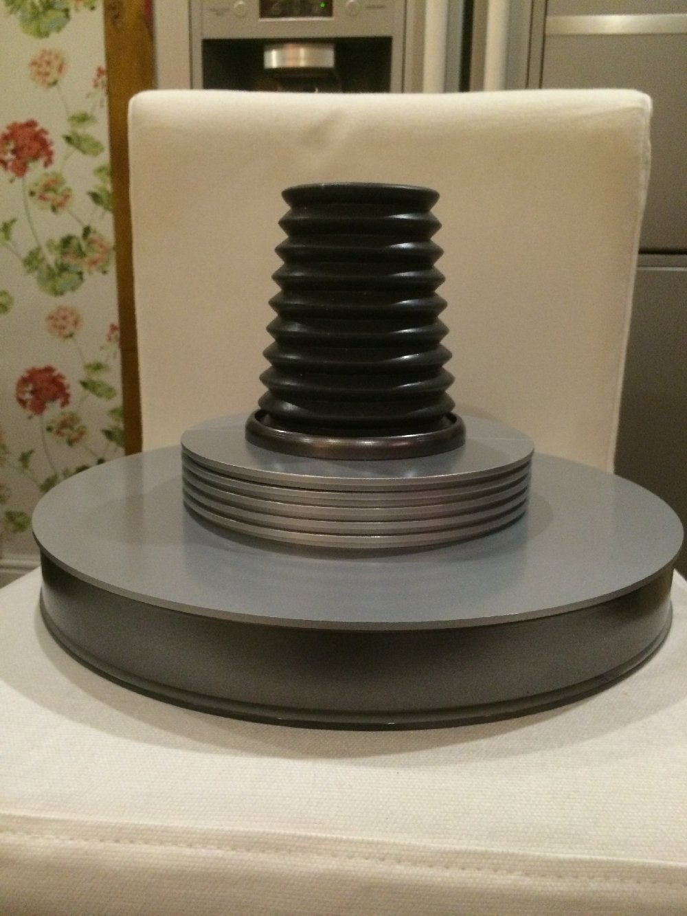
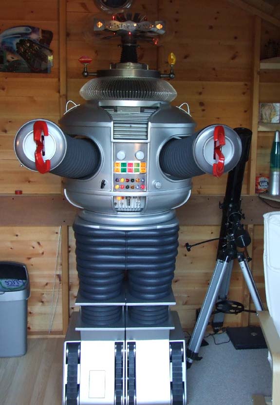
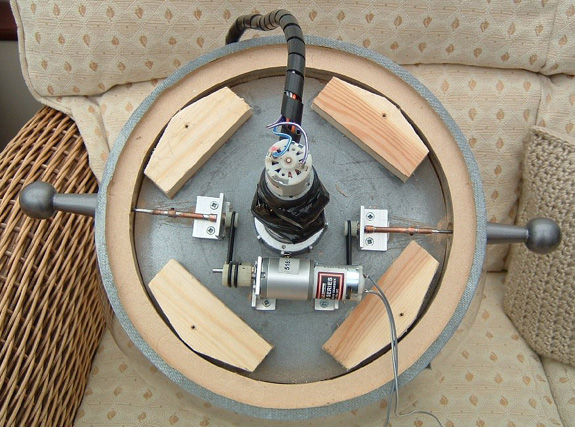
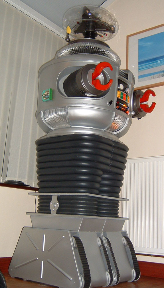
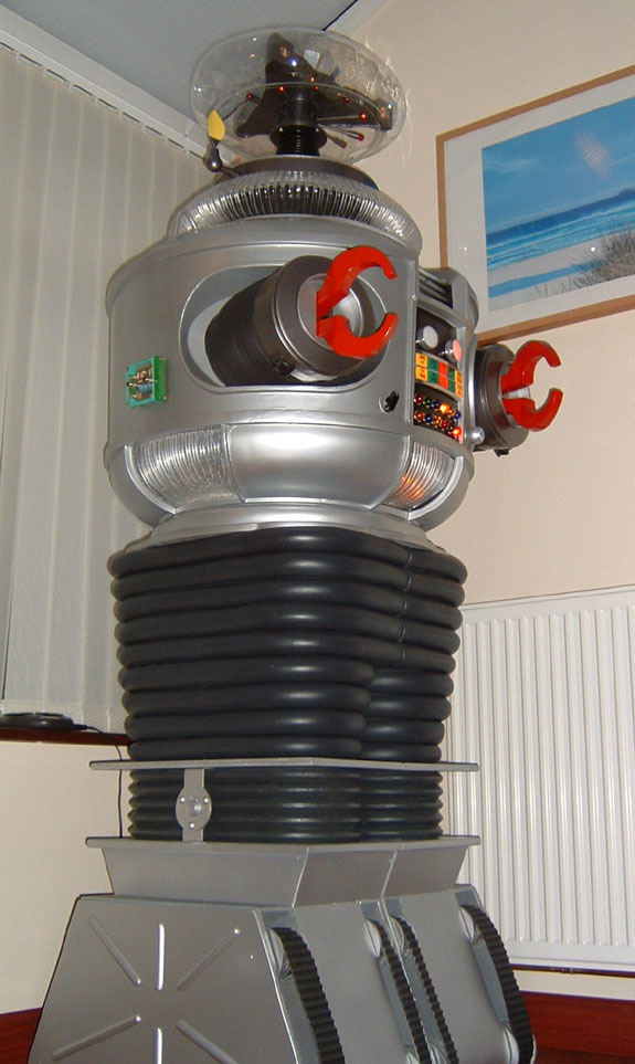
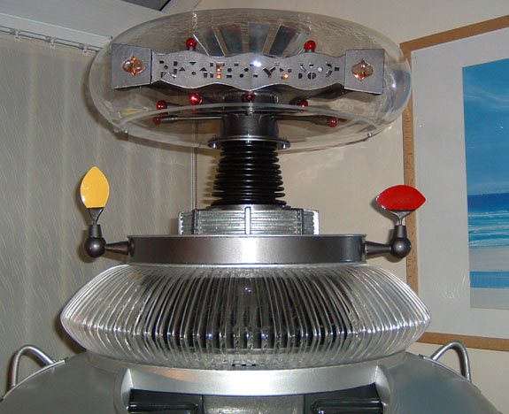
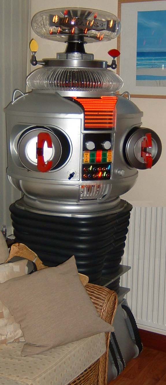
My neck from Will Huff, I made the inner rings for it on my CNC machine.
The brain motor was inserted into the neck pipe to reduce motor vibration & noise.
I added some extra padding in the neck pipe and the motor is silent now.
Neck pipe was spare waste pipe & fittings I had from a plumbing job at home.
The neck is fixed but can easily be modified for movement if required later.
Here are some pictures:
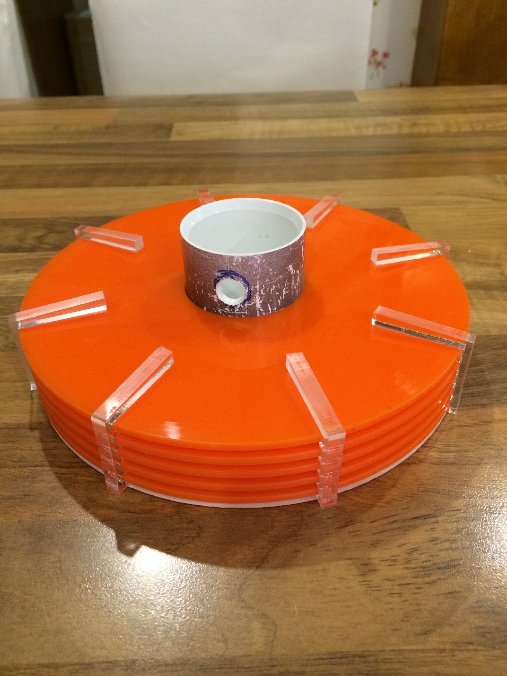
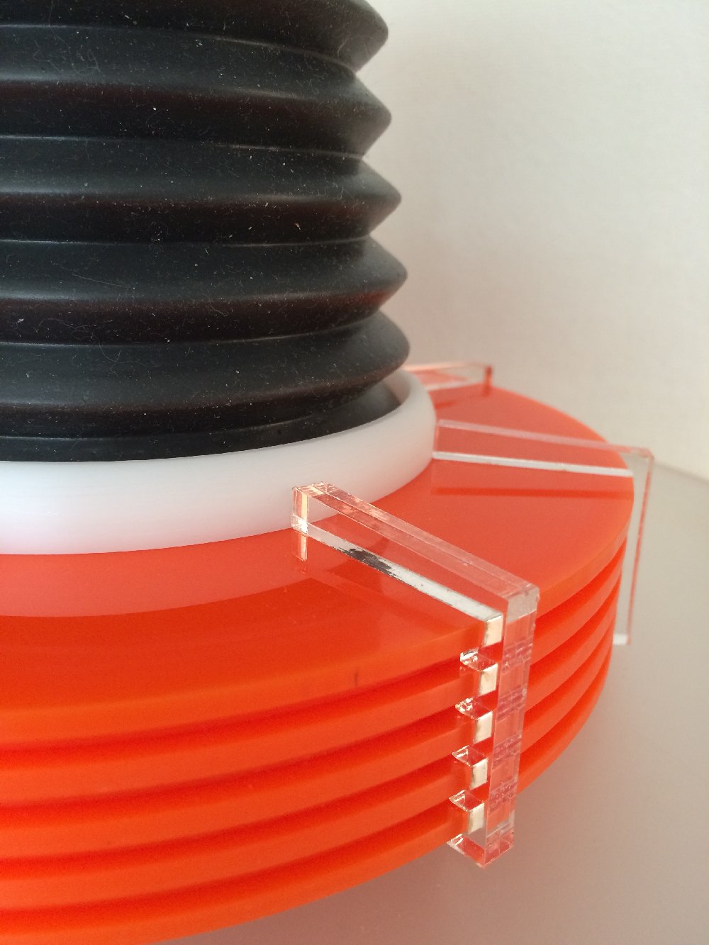
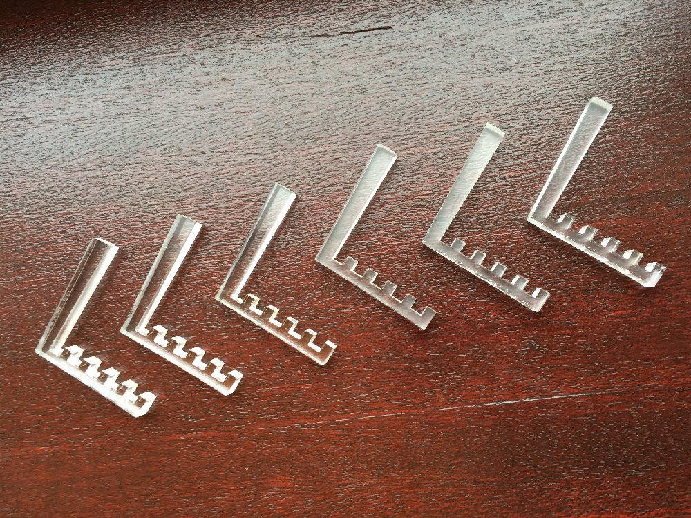
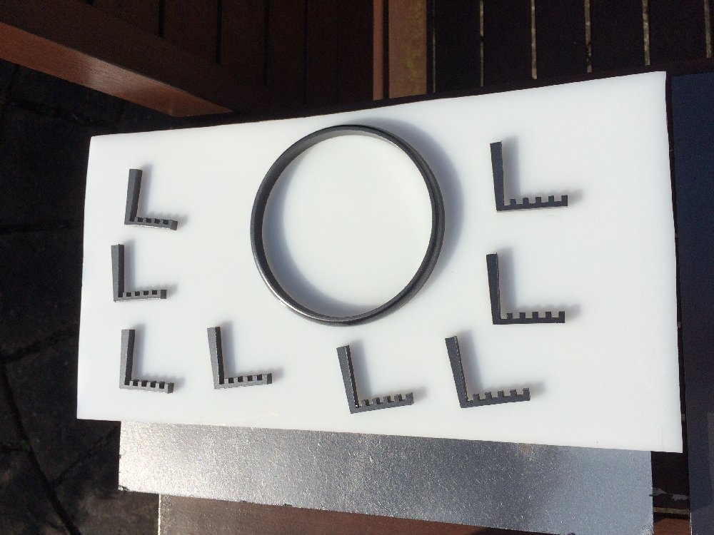
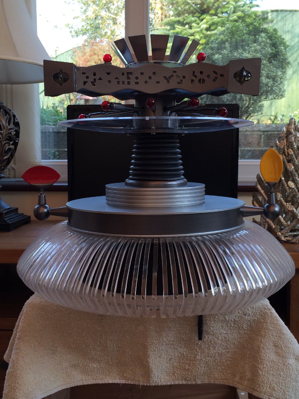
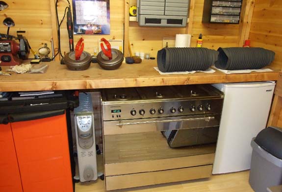
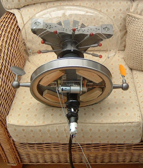
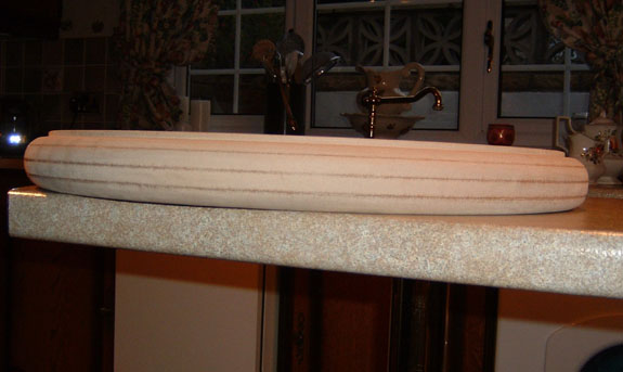
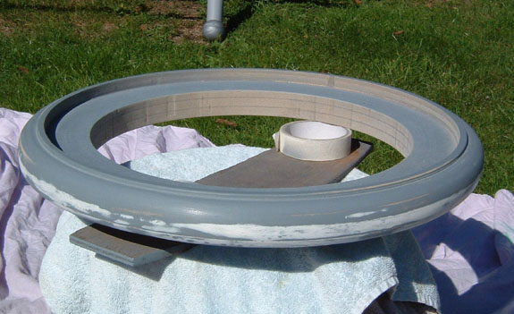
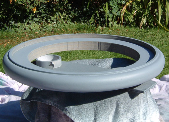
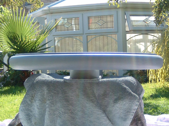
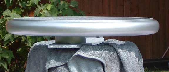
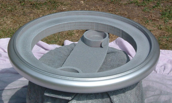
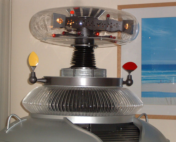
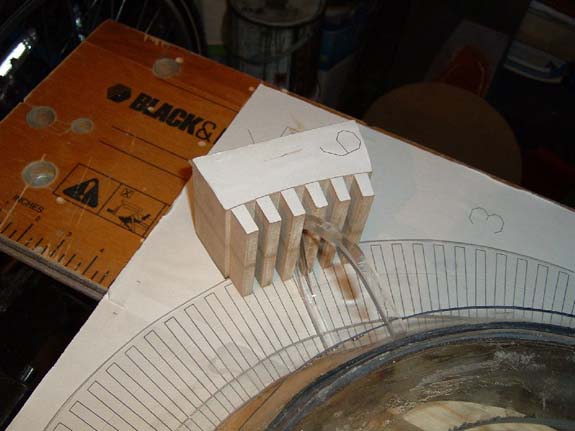
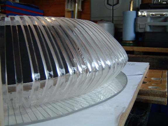
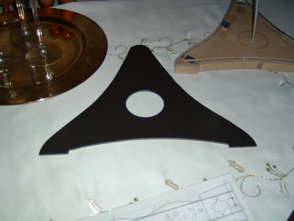
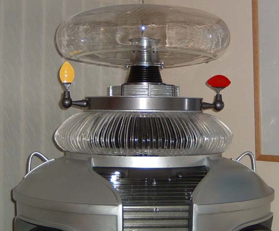
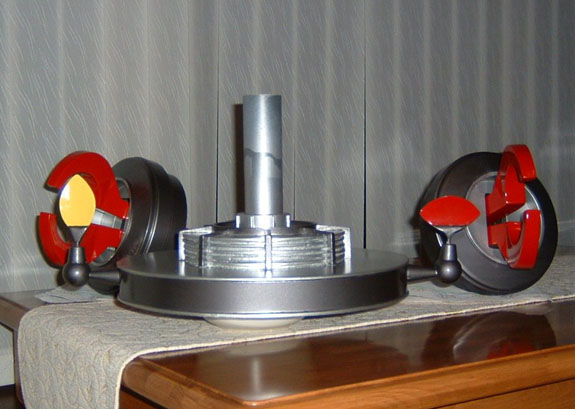
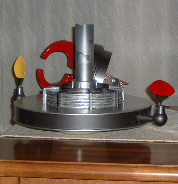
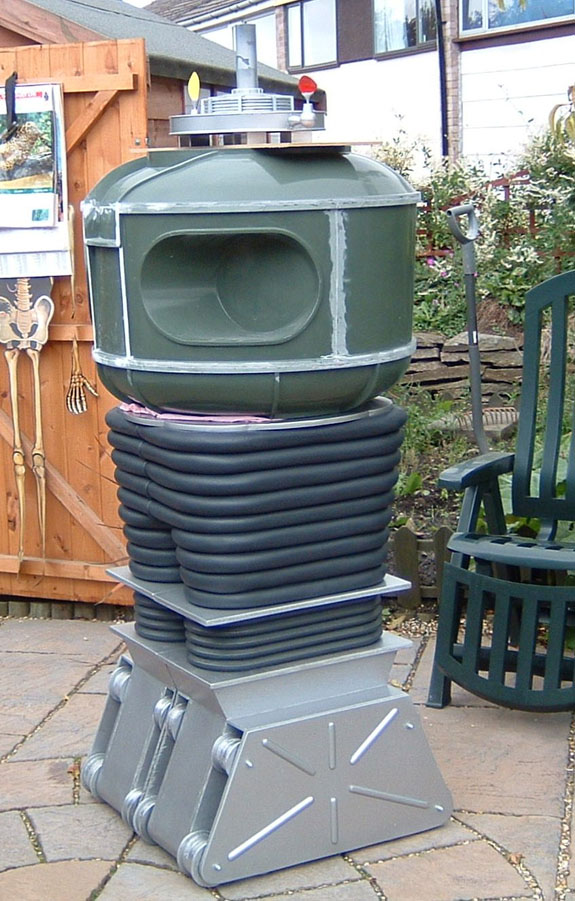
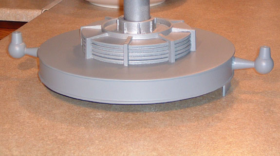
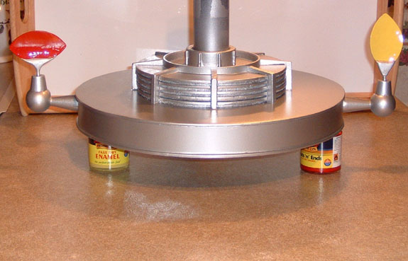
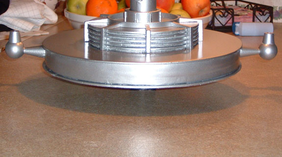
I made my 2nd radar from acrylic, using the blueprints from the club website & the reference material, plus my old one as a template.
The Radar is laser cut Acrylic , the DT department at the School where Julie works really like my B9.
To save time, they let me use their laser cutting machine instead of me machining the parts using my CNC.
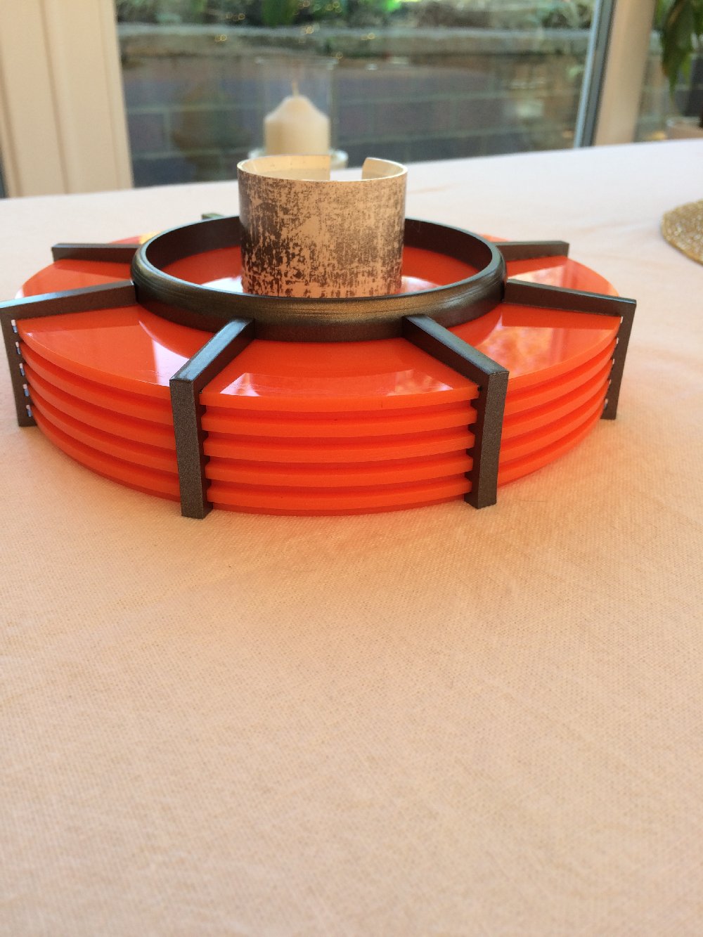
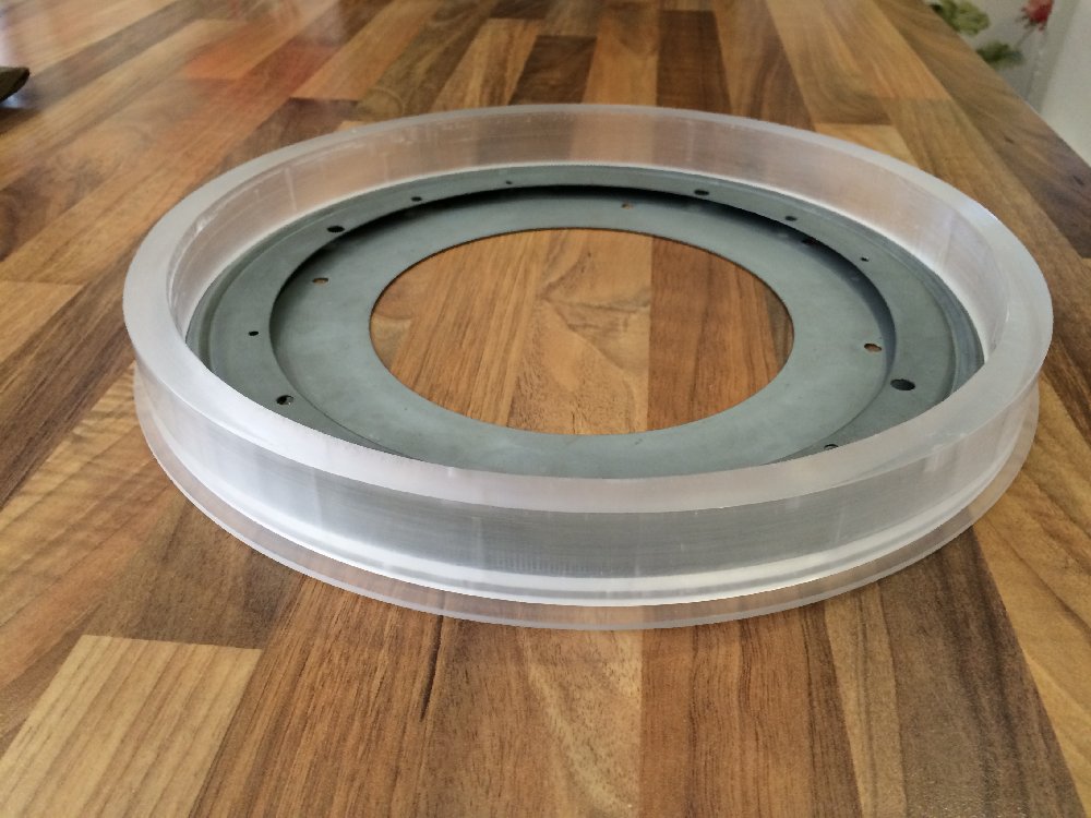
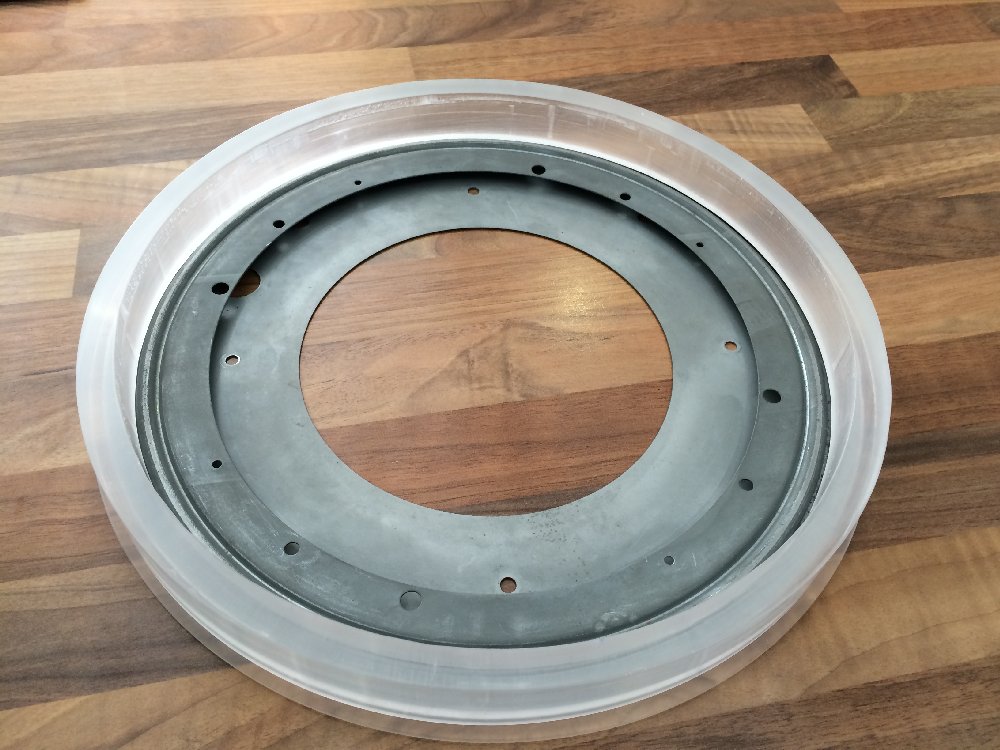
The top radar ring that is at the base of the neck was made on my CNC. It took a while but was the exact correct size.
The large rings would have been too big for my machine & the large middle bit was made at my friends machine shop on a very large Lathe.
Here are some pictures:
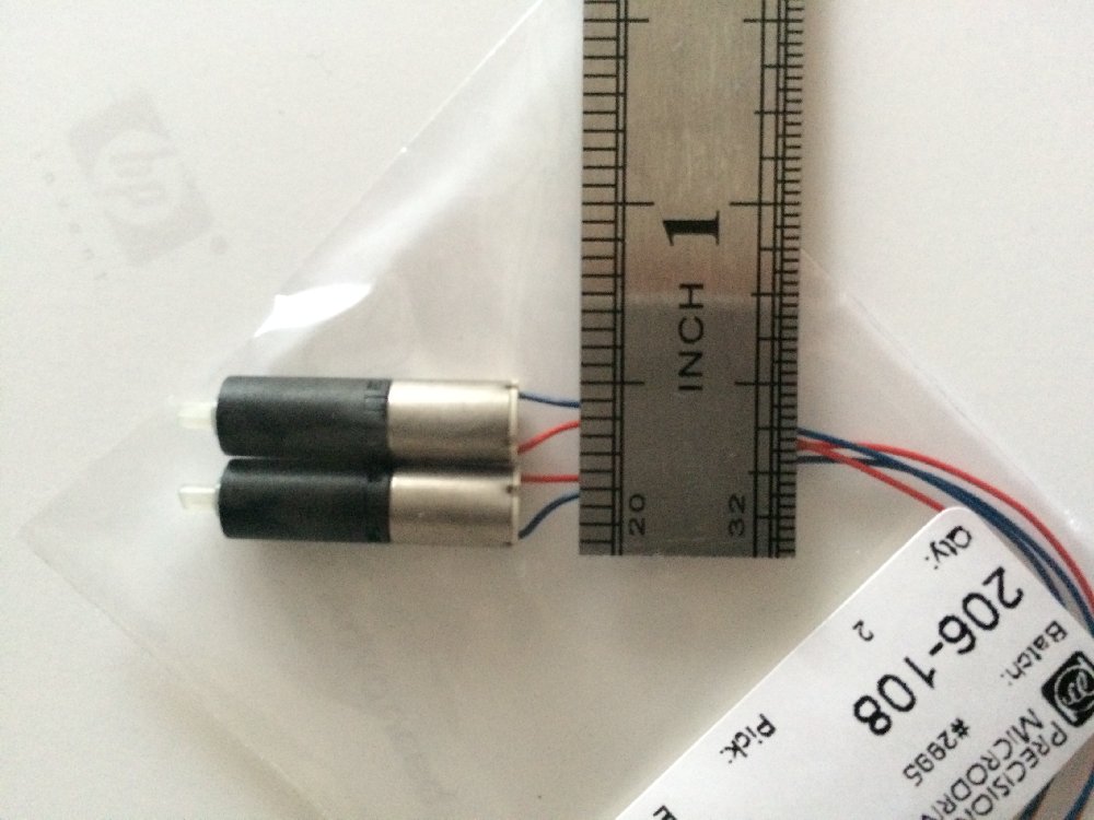
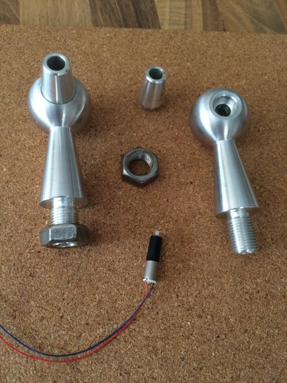
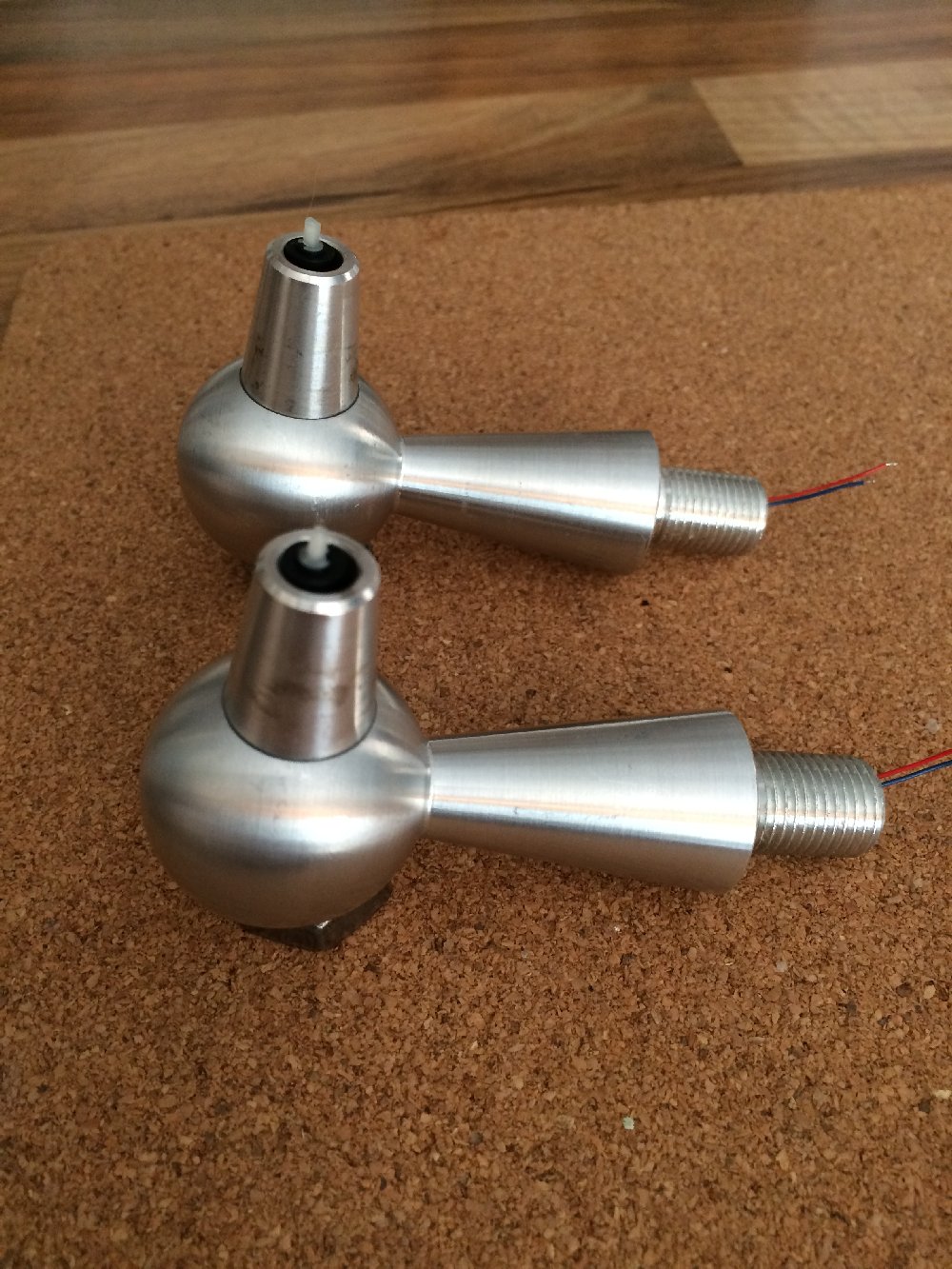
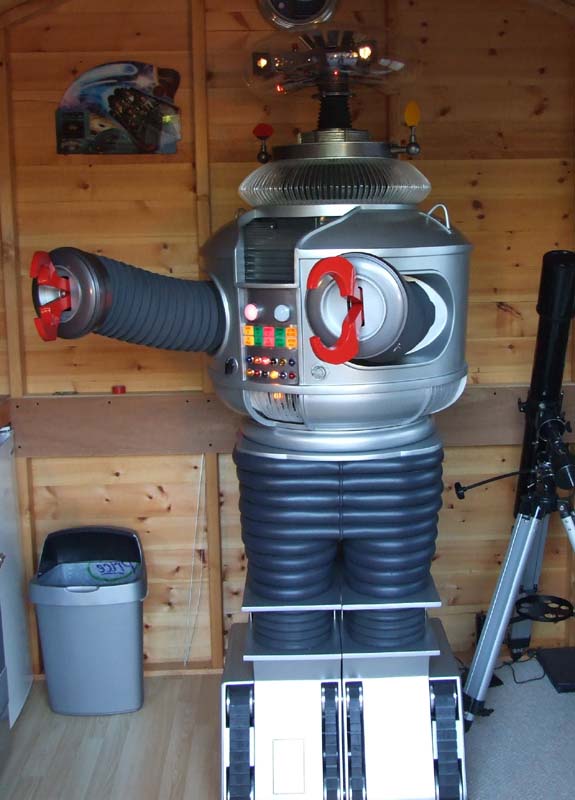
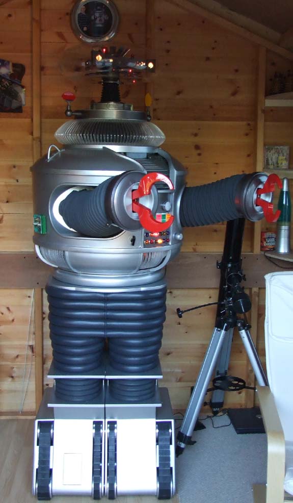
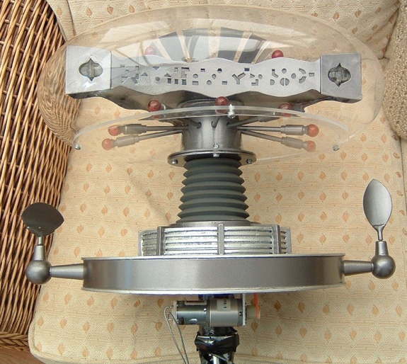
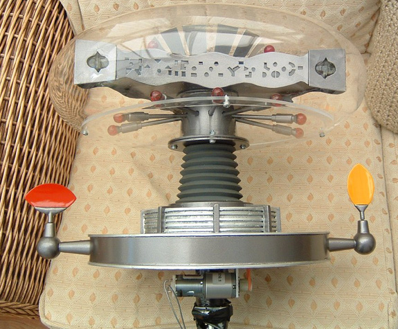
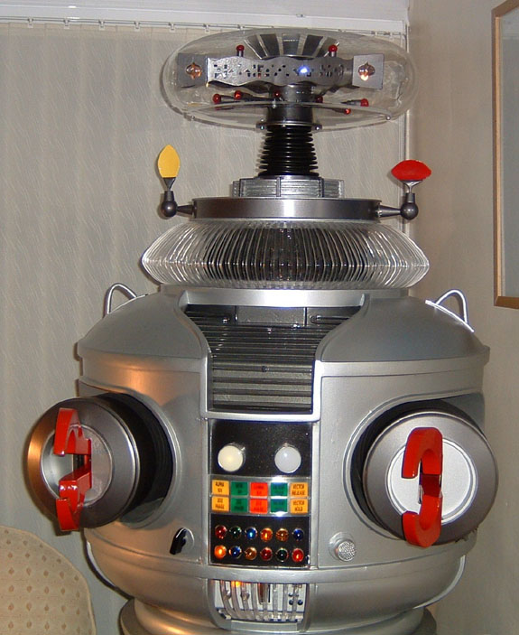
Ears were bought from Craig R. He had a spare set in CNC machined aluminium .
I also bought the small motors that we all use now & used brass bar(7mm OD x 6mm ID) to house them in the Ears.
I also used 3mm OD x 2mm ID Brass bar to attach to the motors for my Radar Ear spinners.
A grub screw was added to the spinners after cutting a small thread in them.
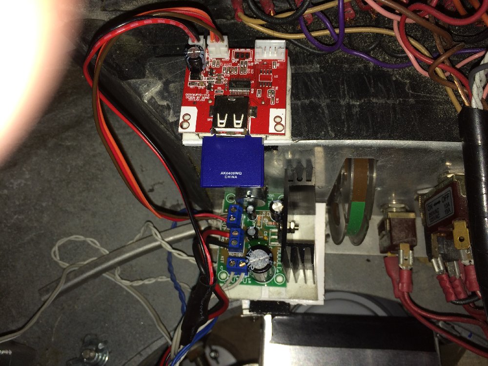
I also rewired the Brain but did not photograph any of the work unfortunately.
I also added a mono amp, jukebox SD memory card music board & small speaker. This is for the Robot noise only.
the volume is controlled on the front programming bay panel.
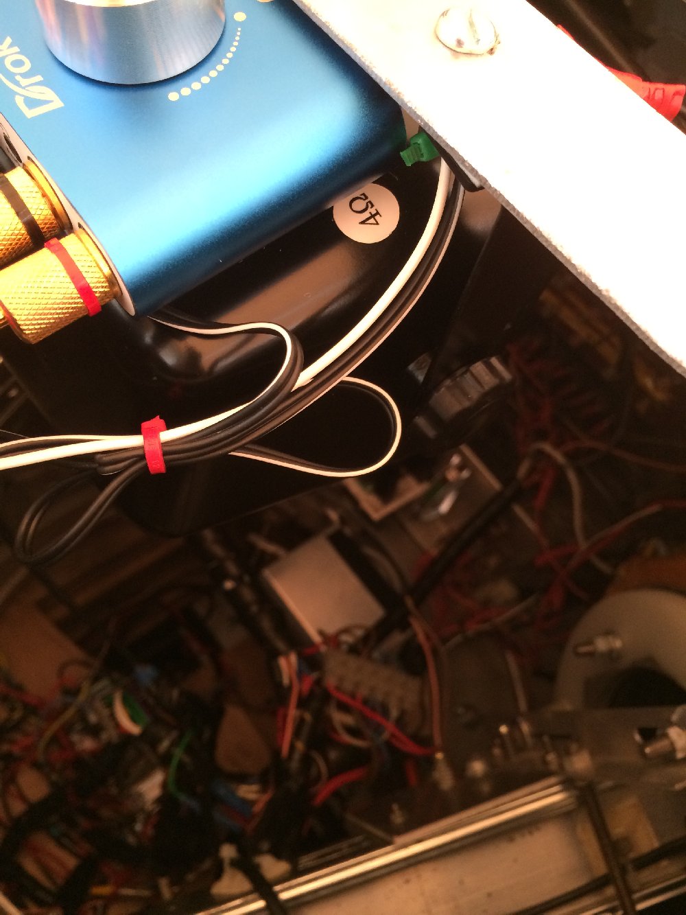
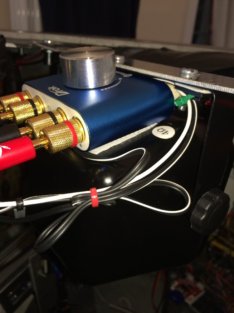
I upgraded the main robot sound system with a high powered Stereo Bluetooth amp & 60watt Speakers.
Here are some pictures:
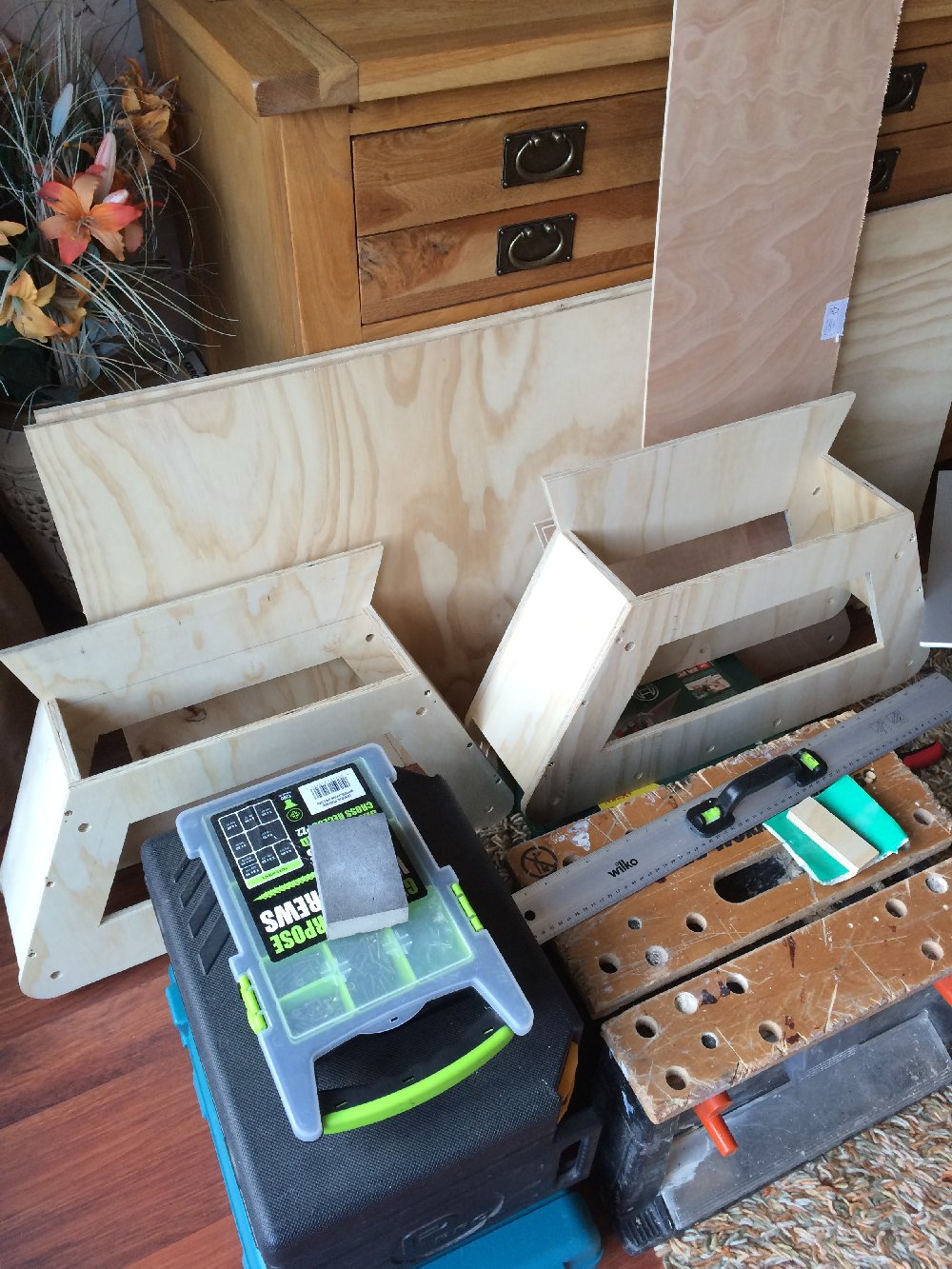
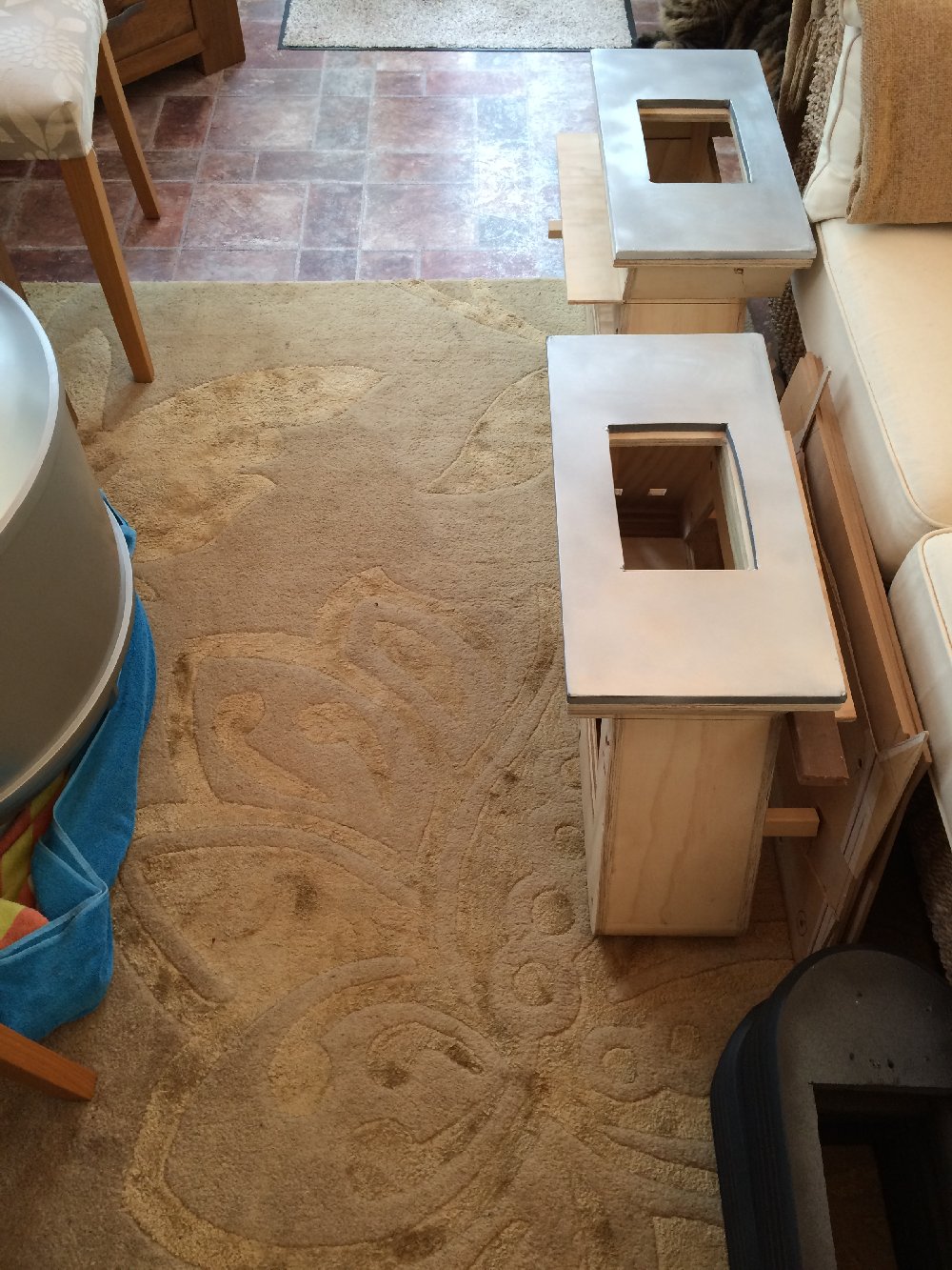
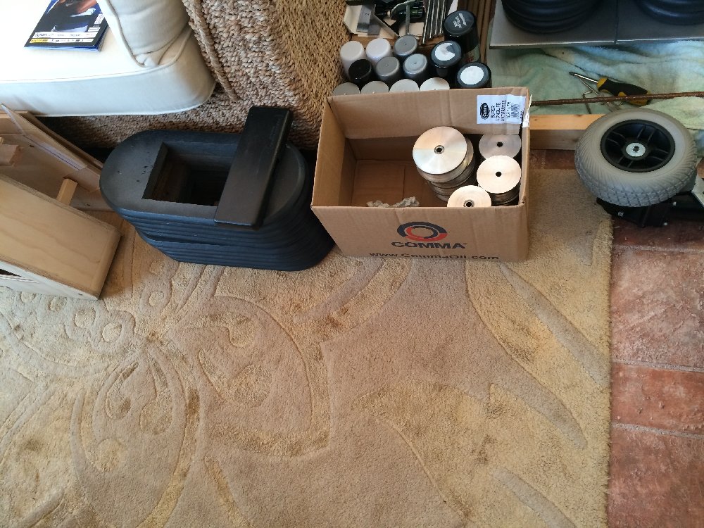
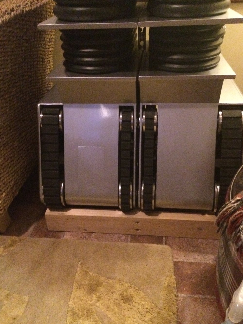
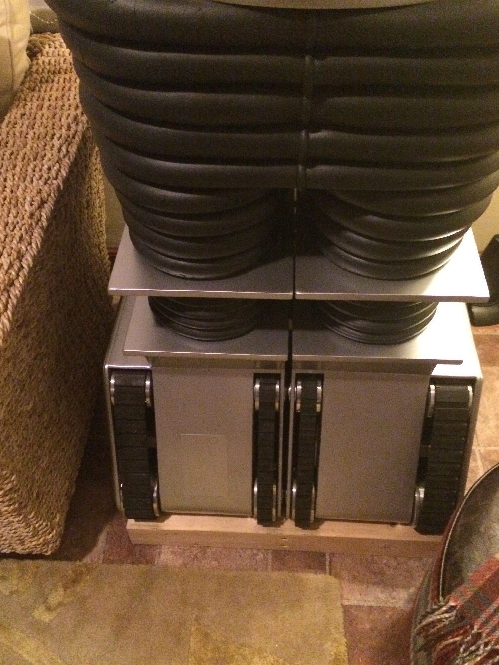
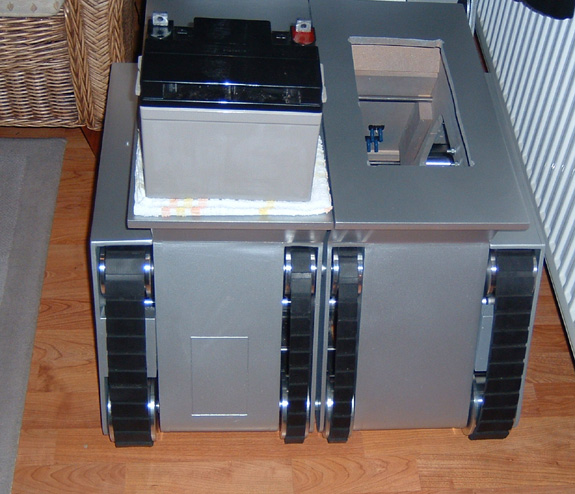
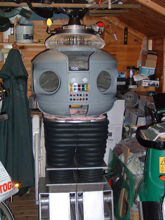
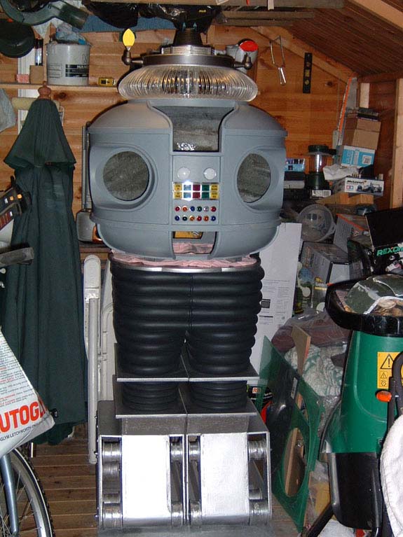
I made another tread section (3rd one).
This one is plywood with plastic & aluminium skins.
Not much to say on this but I put new oil light bushes in the wheel centres, bought new wheels & tires for the drive motors.
My treads are slightly raised on the front to enable the drive wheel to run freely.
The treads rest on the rears for stability & to make the rubber treads move.
I have had this setup working since 2006.
Here are some pictures:
2008
12/20/2008
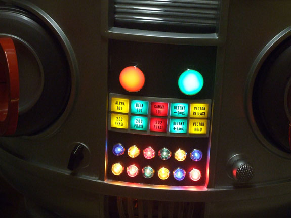
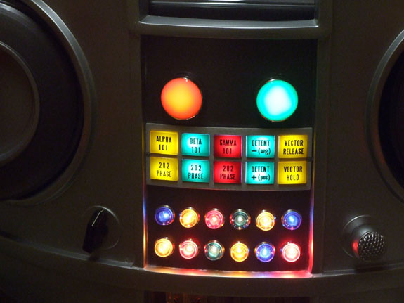
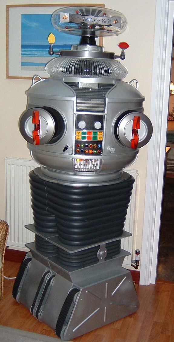
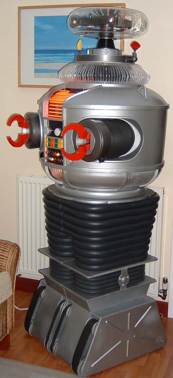
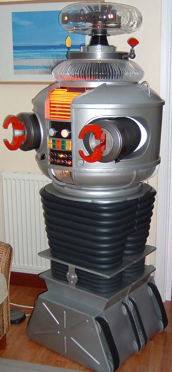
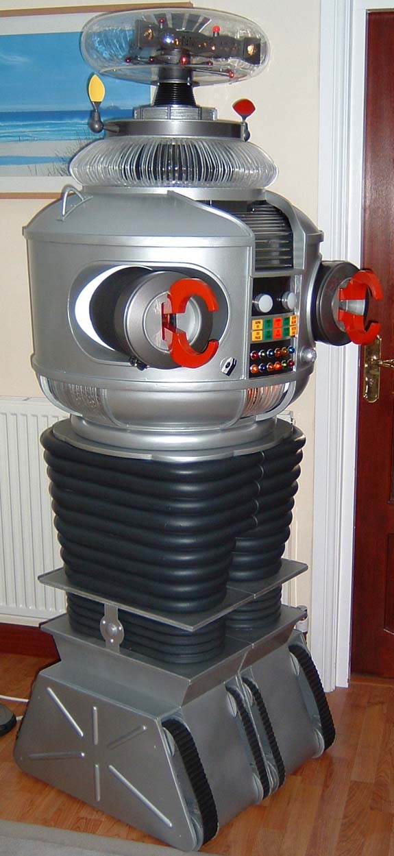
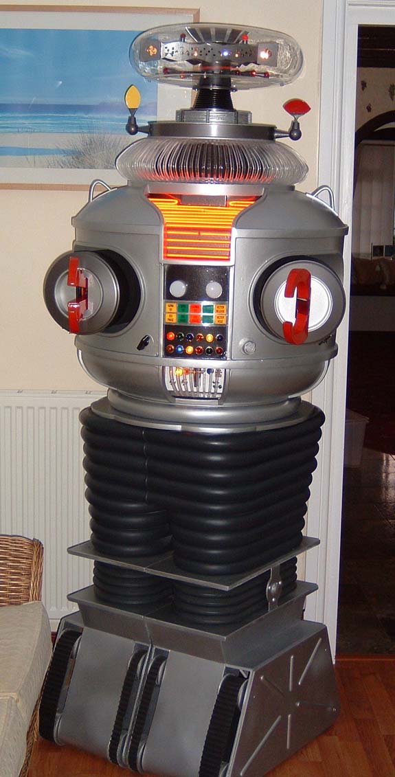
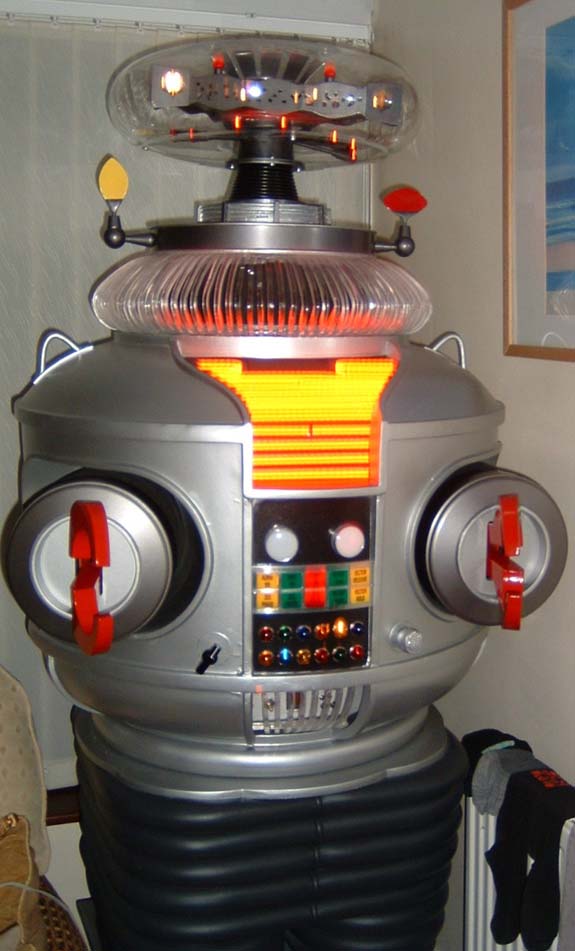
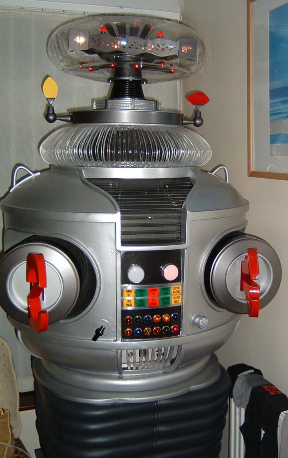
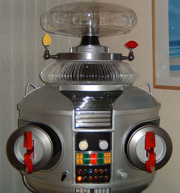
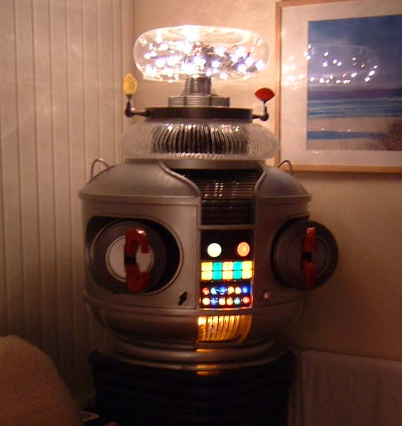
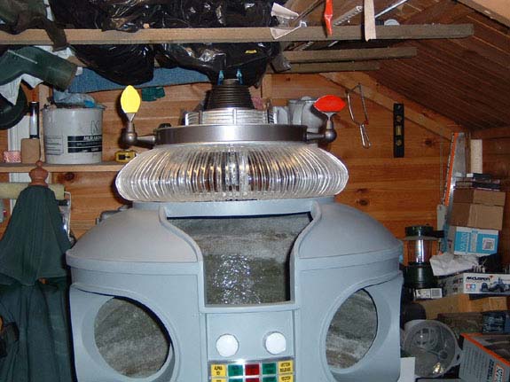
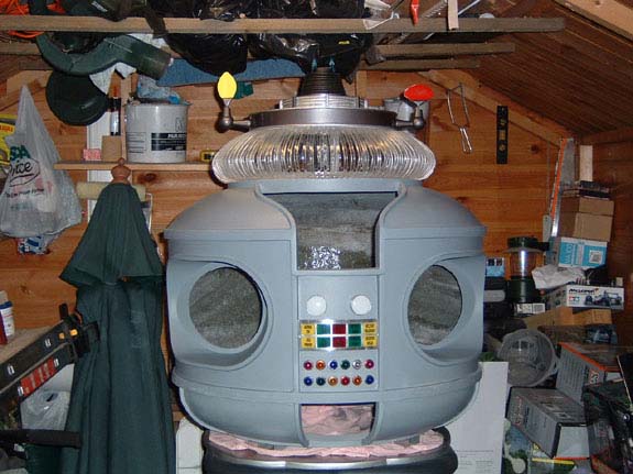
I have fitted the bezel all is working fine with my B9 here are
the updated pictures.
12/13/2008
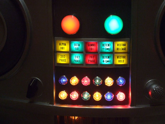
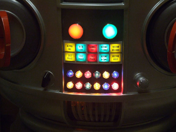
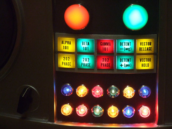
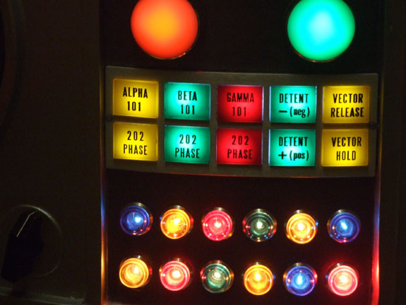
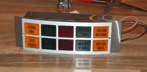
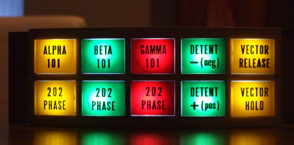
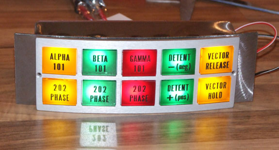
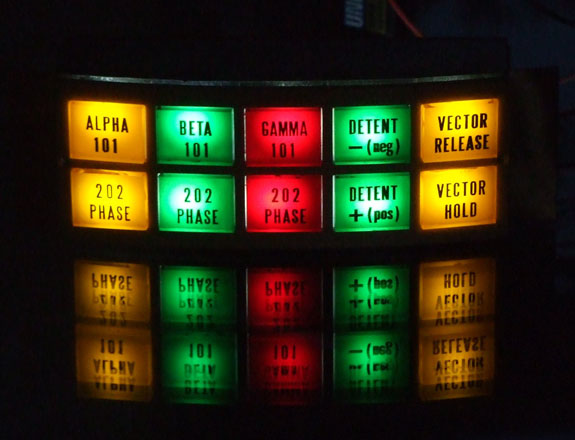
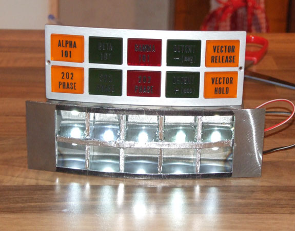
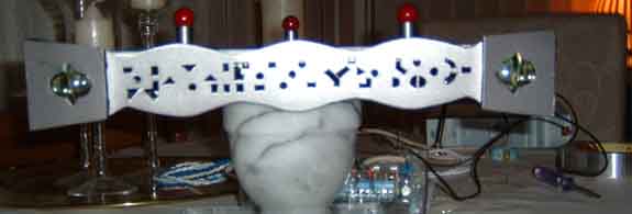
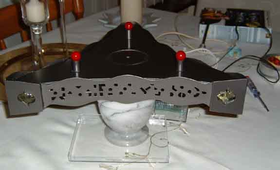
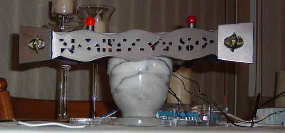
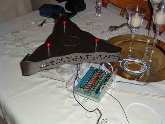
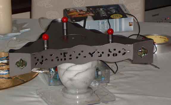
I have at long last completed my bezel button box
I have divided
it into 10 sections and each one has a 5mm ultra bright led in
it I chose the narrow beam to attempt to recreate the effect of
the replica
To my great
amazement I have managed to get the desired effect
Here are some
pictures of the bezel and box – I will be fitting it this
weekend

2007
11/26/2007
I hope you all had a good thanksgiving Holiday.
Well here
we go I hope I explain this ok as the video shows everything but
I am sure you will have questions.
Here is the
Youtube video
Right – I’ll
start with the list of components I used for this:
1 pair of nylon Wrists
(CNC machined)
2 pair of nylon claws
(CNC machined)
2 Maplin motors 12
volts ratio516:1 (as seen on the b9builders website under off
the shelf)
2 pulleys 2 springs
and some steel plate and 90degree steel section for the brackets.
I initially started
with the new nylon claws; the 4 were made as per the Dave Painter
drawings:
Then I had
to modify them to suit the mechanism – sorry you will need
to see the video attached but the only thing is that
the lower claw has been cut off a lot shorter than the top one
and the end of the lower claw has been rounded in a very similar
way to Mike’s Replica claws but without the teeth.
Next was to make the
mechanism which is again shown on the video
The Pulley is attached
to the top of the motor then a hole is drilled on the edge and
a bolt is inserted with a very small sleeve and bearing then a
piece of steel was added which was then attached to the top claw
via the bracket (seen in the video) a bit like a big end in a
vehicle engine. The top bracket is then attached to the wrist
with the spring to allow the claw to move all of the work is done
through to top claw.
On the far side of
the claws are 2 more pieces of steel which are joined between
the claws and have a pivot point to allow the bottom and top claw
to move at the same time the rounded of part of the bottom claw
is also moved when the rear of the top claw is in the downward
movement.
Again apologies to
anyone if this was a bit confusing, I must say it seems a lot
easier to put the pieces together than explain how it all works.
I have one note on
the springs I used I decided that all I would need would be for
my B9 to handle pretty light objects so I used quite a weak spring
This however can be
replaced with a stronger one if needed; i have kept with the ones
I used because if you put your hand, or more importantly a child
was to put their hand in the way of the claws they won’t
get hurt as the claws will still run but not try to crush.
I was still able to
get my B9 to hold a can or bottle or letters etc.
He was able to hand
the envelope over with no problems at the award ceremony I attended
the other week and from my point of view that is fine
When I was at the space
centre he did take a soft toy from a little girl (who was being
held up by her father) passed it to me then I gave it back to
him and he then gave it back to her. That was a good test too.
Well I hope this covers
everything and please let me know if you need any additional info
or help on this.
I have one
final thing to say and that is if any of you have information
and diagrams of making the B9 slump forwards when the power pack
is removed and stand up again when it is re-inserted please let
me know as I am currently looking for a set of second hand Dewey
style rubber legs and will do this as my final upgrade (for now).
11/08/2007
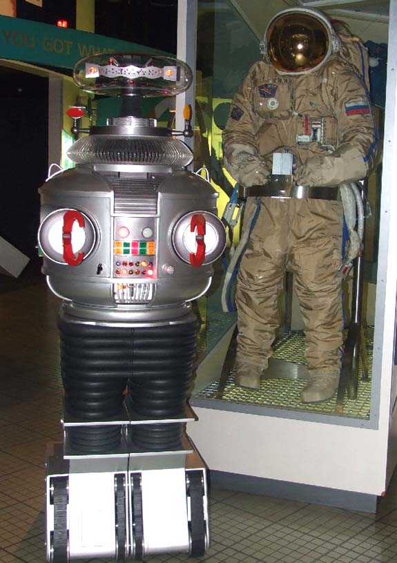
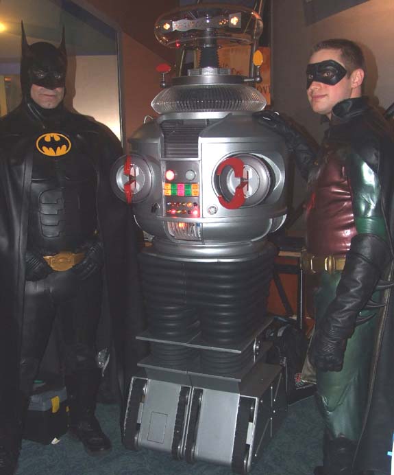
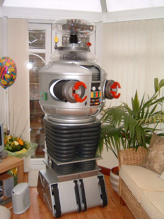
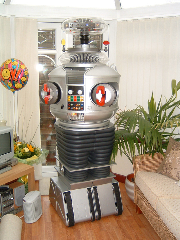
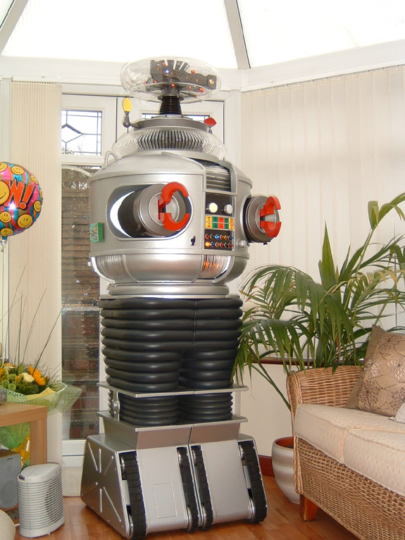
Here are some Photos of my B9 while attending the Sci-Fi Weekend
at the UK National Space Centre.
07/04/2007
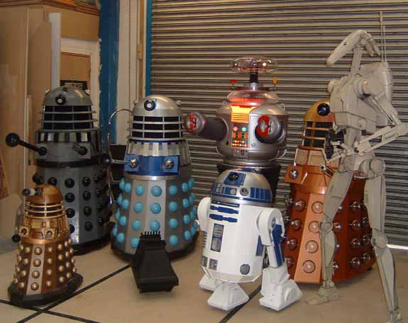
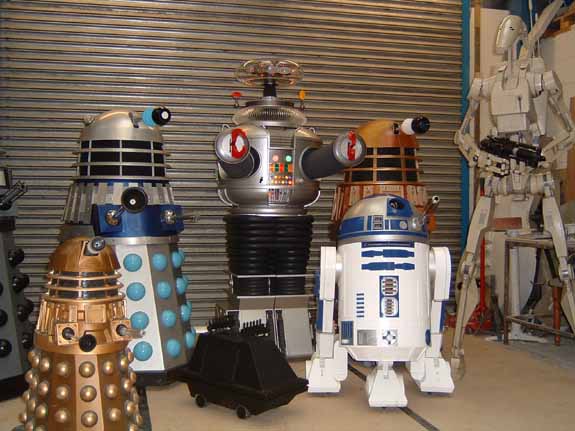
Here are a couple of pictures from the UK robot builders meeting
I attended Saturday. There was a lot of interest in
my B9 by the way.
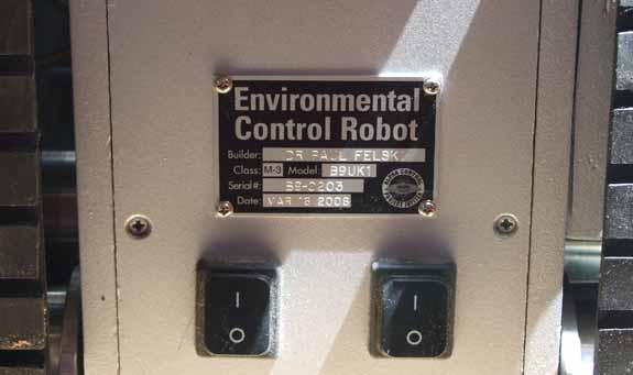
I have at
last installed my dataplate, Here
are a couple of pictures:
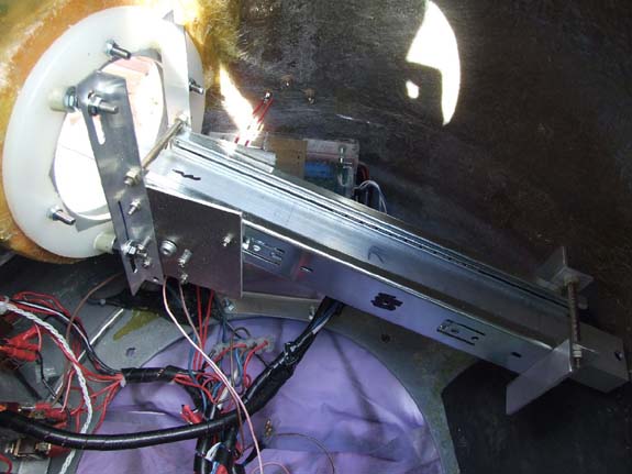
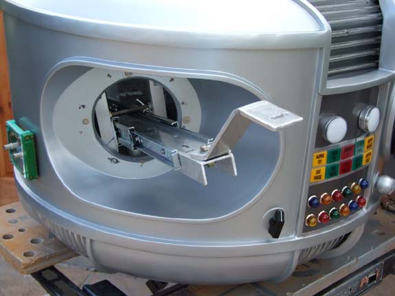
05/22/2007
Hello everyone
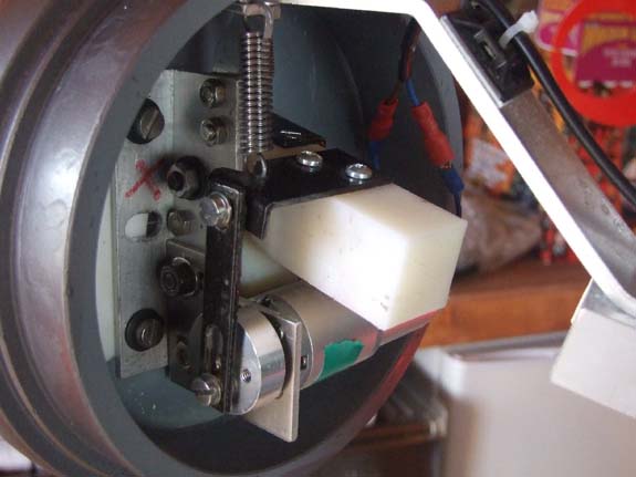
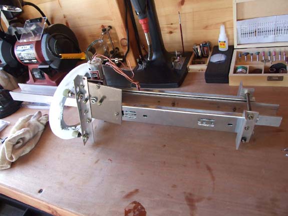
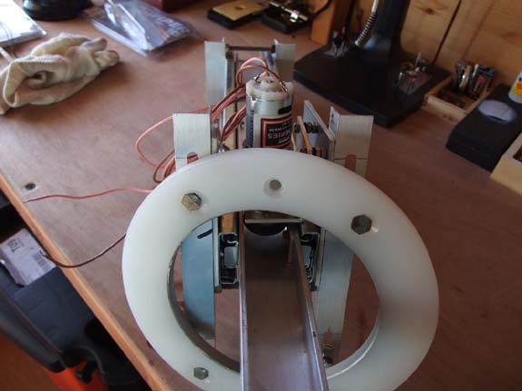
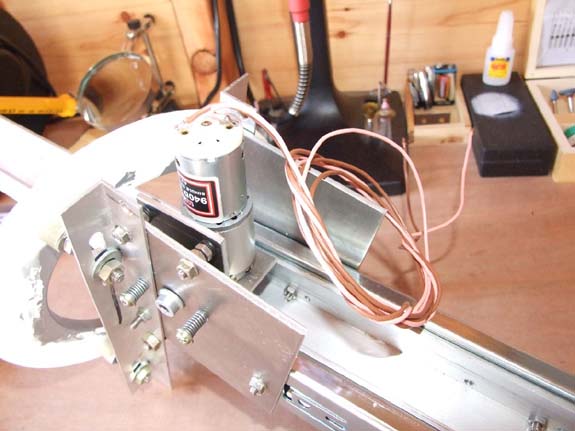
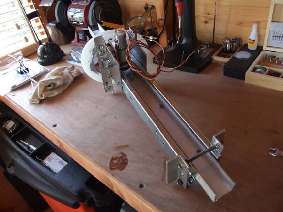
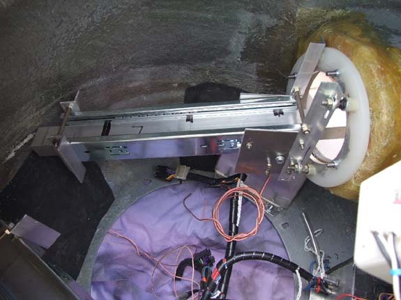
Here are my pictures of the arms mechanism it looks complicated
but it is only 2 14” drawer runners with some aluminium
plates and another of my 516:1 motors as I used on the brain torso
& ears they are very good motors so it should last for a while. The
2 motors are attached to a speed controller as seen I one of my
pictures enclosed.
Please let me know if can provide any additional info on this.
Paul
Hi-Res
Photos Zipped
05/18/2007
Hello everyone,
Please find attached 2 small videos of my completely motorised
B9. I have spent quite a few weeks now getting the arms
motorised and today they were fitted. I have many pictures
of the process piece by piece. I can only say that my B9
is really alive now – It was very satisfying to see the
arms move on their own. I
hope you all enjoy the videos.
Paul
Video
# 1
Video
# 2
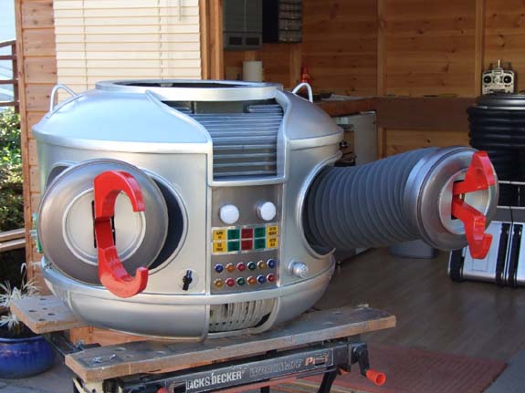
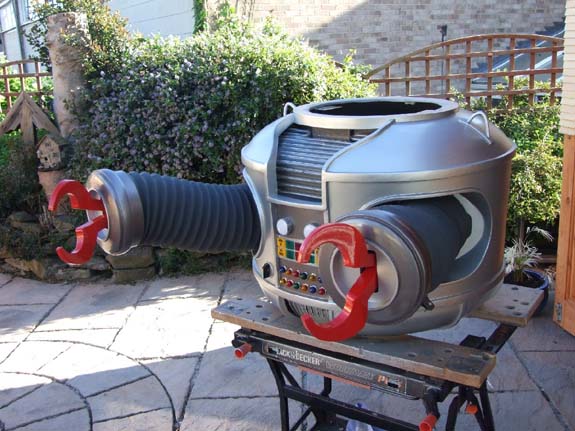
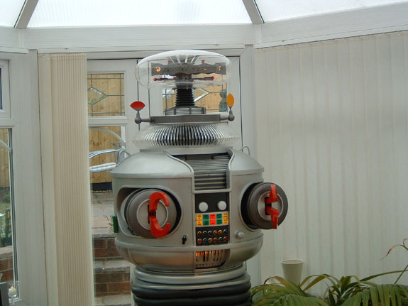
03/28/2007 Hello
All
Just
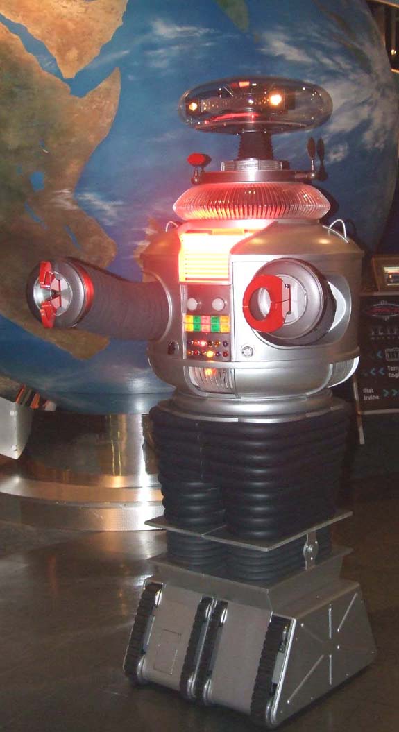
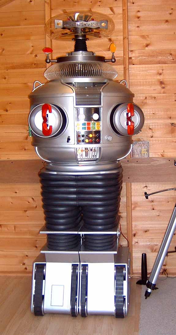
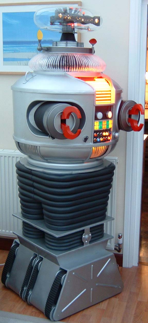
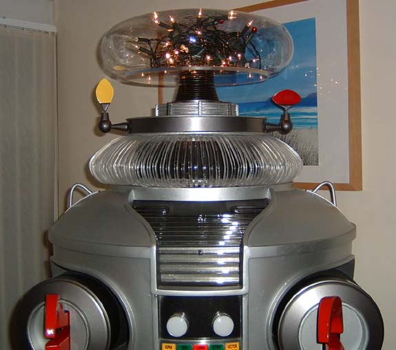
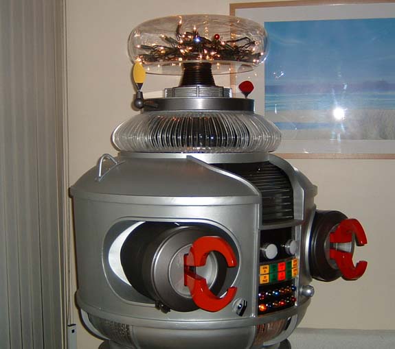
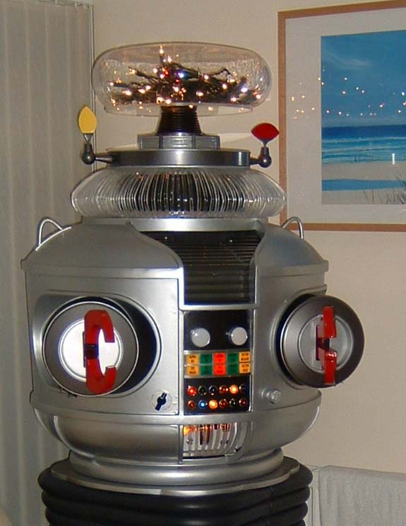
a final picture of my B9 with his new bubble in place. Becky
(my daughter) took this picture, tomorrow we start fitting my
new arms from Vince with the mechanised components. I’ll
keep you posted on the progress, hopefully I’ll have some
DVD footage to bring to Denver as I am going to do some filming
of the B9 in action in the garden.
Paul
Here
are some pictures of my B9 wearing his new bubble.

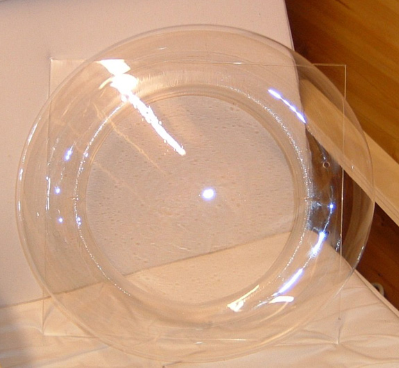
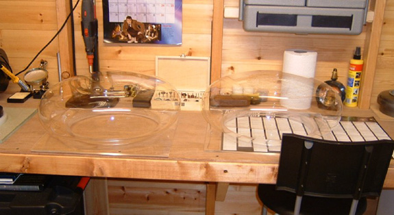
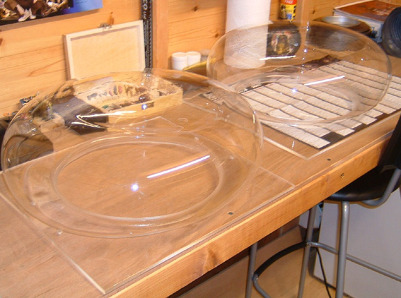
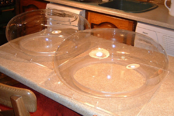
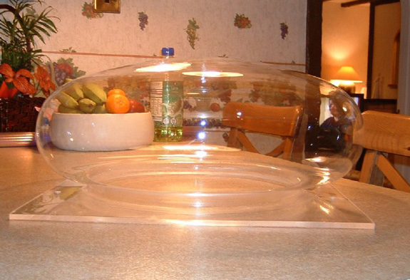
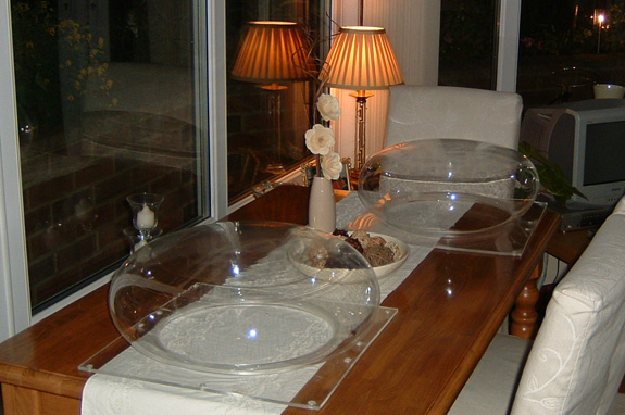
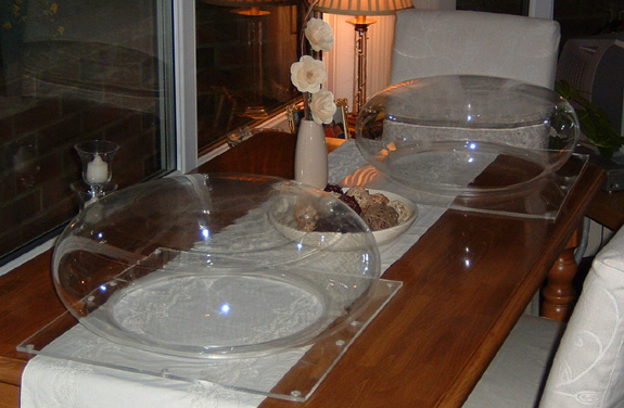
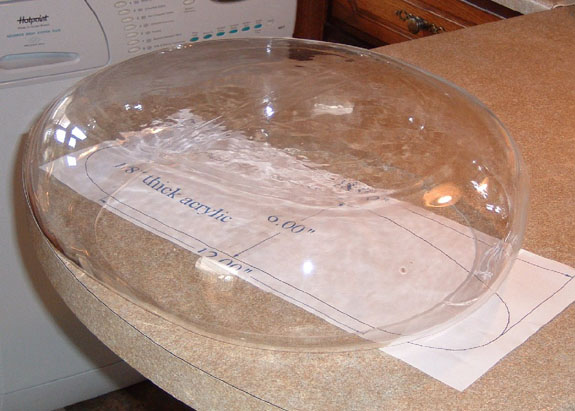
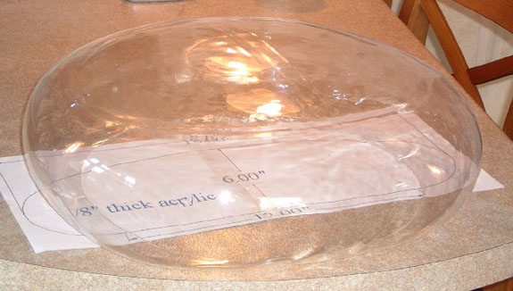
03/09/2007 Hello
All
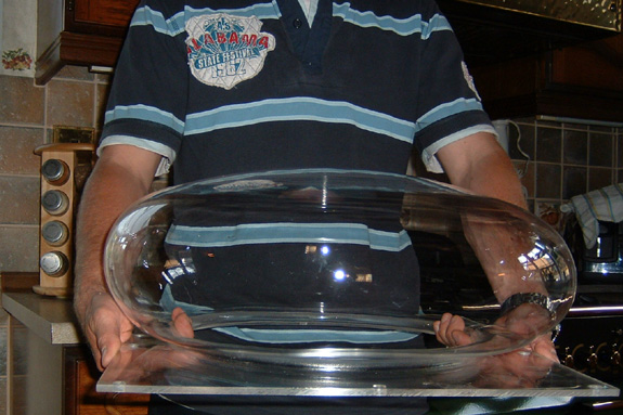
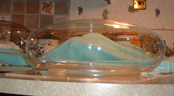
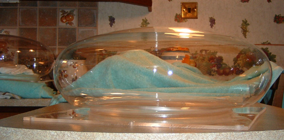
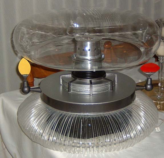
As you
all know I have been trying for quite a while to create an 18inch
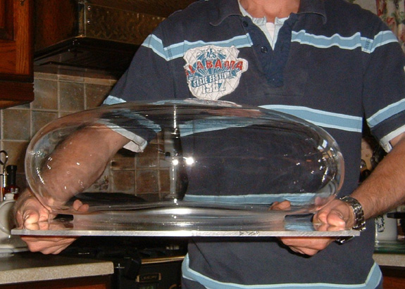
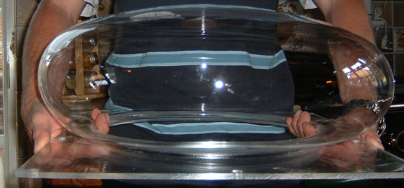
Bubble for my B9, well tonight I have had 100% success.
I blew
2 bubbles and they both came out great.
Here
are some pictures – my B9 will be wearing one of them very
soon, but I will have some spares, as next Thursday I will make
some more 2 maybe 3.
I must
say this has been a great sub project for me and I have enjoyed
every moment of it
Paul
(B9-0203)
2006
12/19/2006
Hello Everyone,
I would just like to wish you all a very happy Christmas and prosperous
2007!
Thanks again for all the continued help and support.
Paul
(B9-0203)

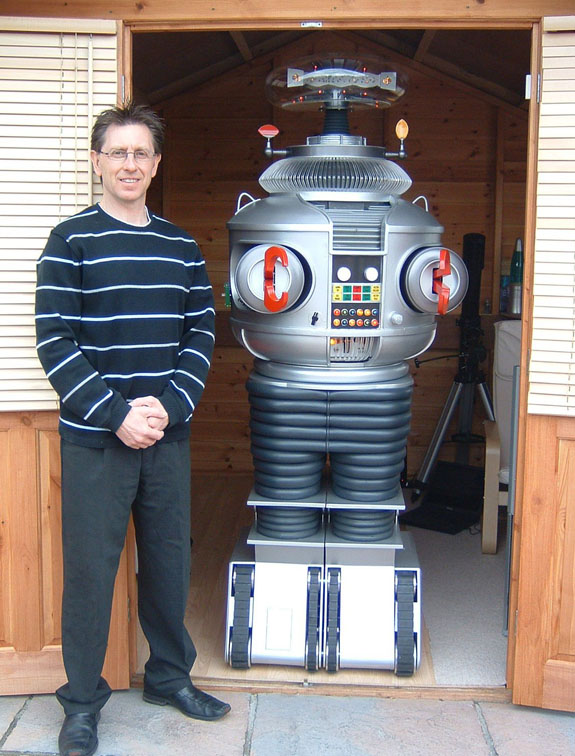
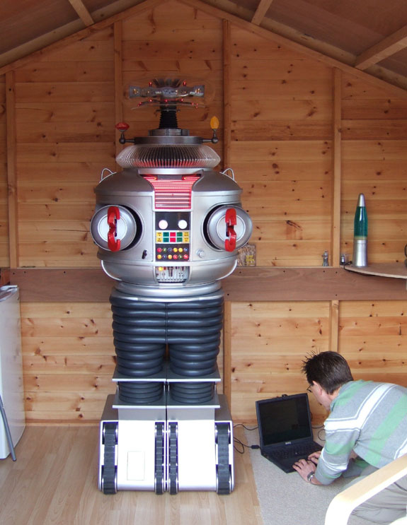
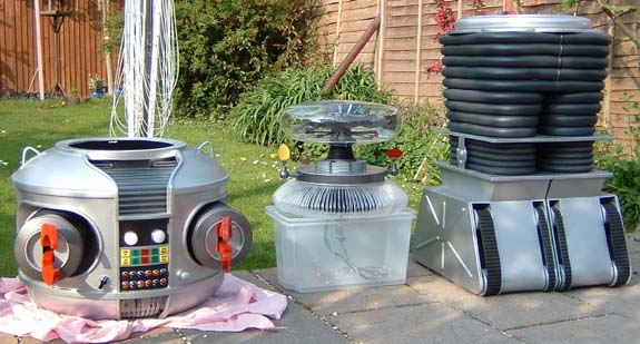
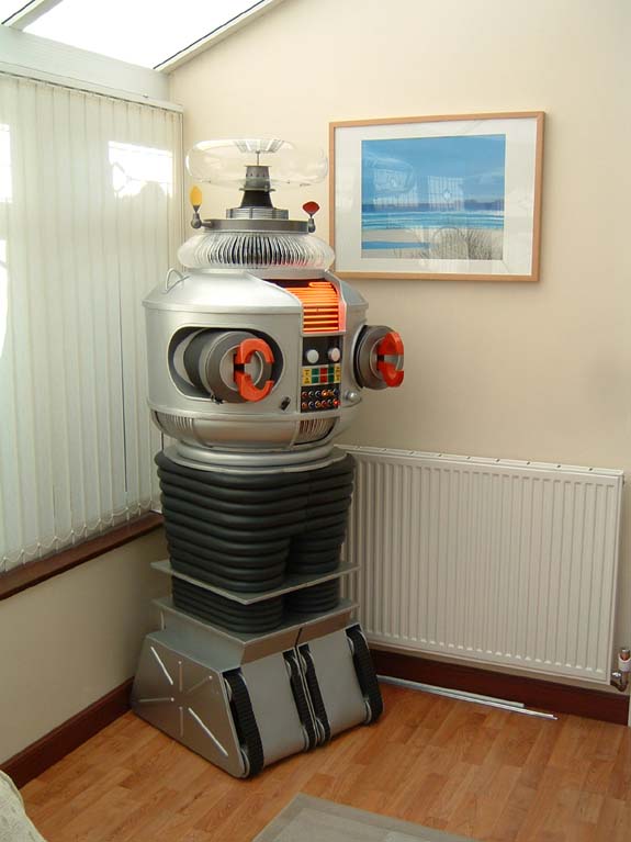
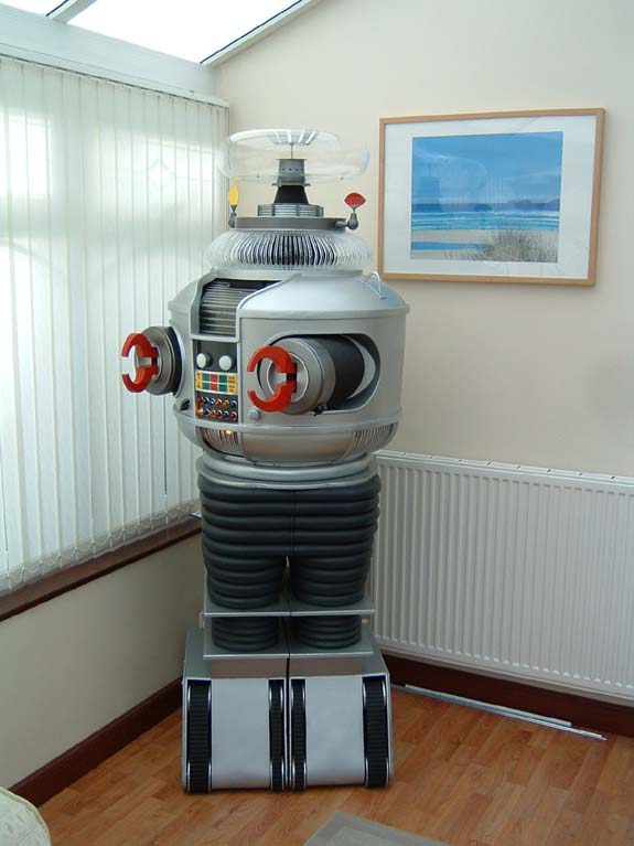
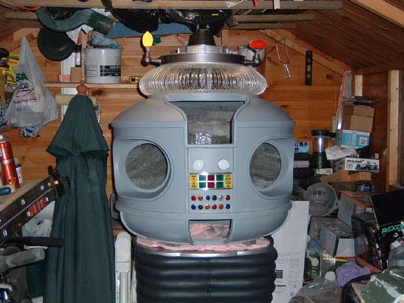
My B9 has a new home – a 16x12foot workshop in my garden
08/20/2006
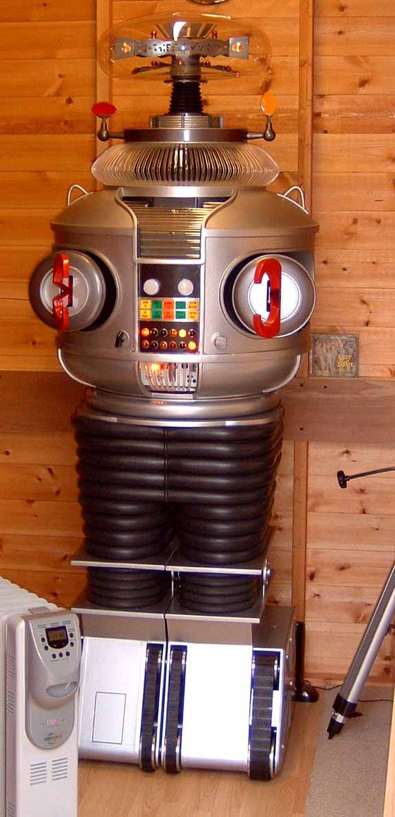
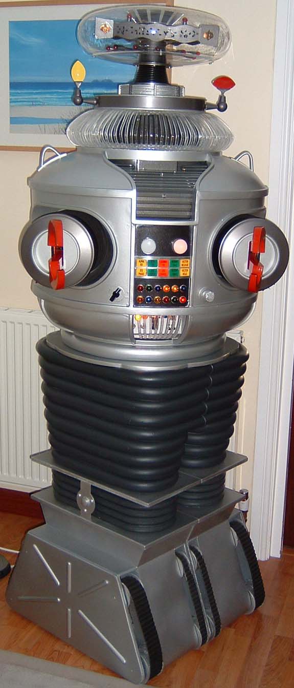
Here are some pictures taken of my B9 a couple of days ago.
I have
upgraded him with new nylon wrists and claws; the new bubble is
in place with its new bottom plate.
The
motorised ears and new sensors are fitted.
I am
still working on getting the bubble sorted but the only problem
I have is with the acrylic at the moment.

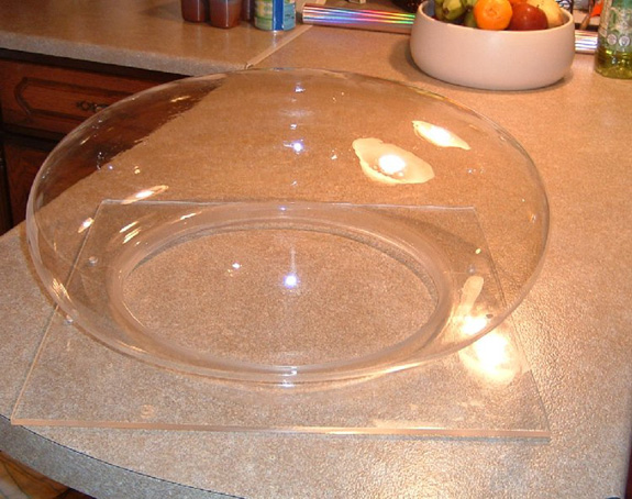
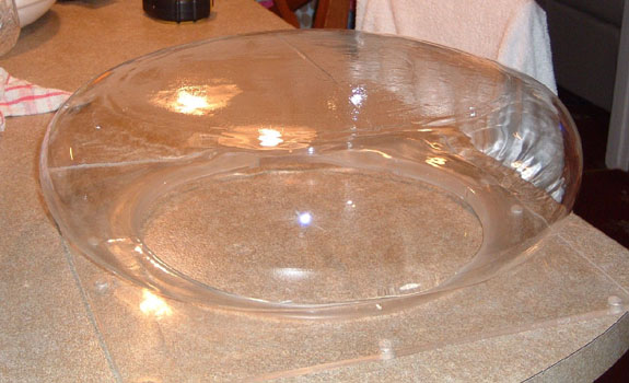
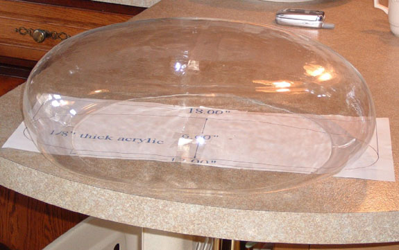
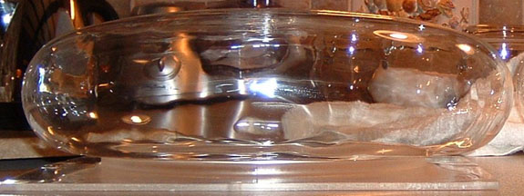
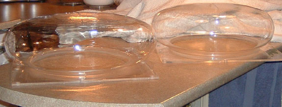
06/17/2006
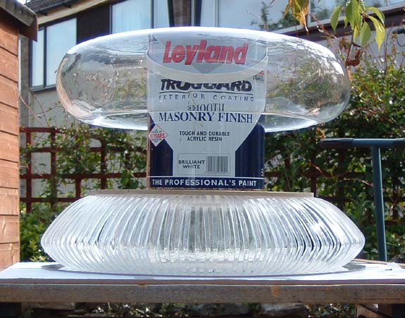
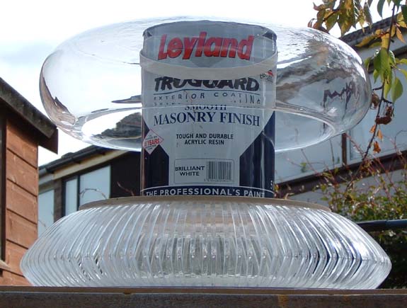
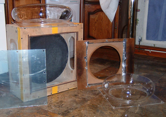
Bubbles
Hello everyone,
As you all remember I was looking at blowing a bubble for my B9,
well tonight I have had some success.
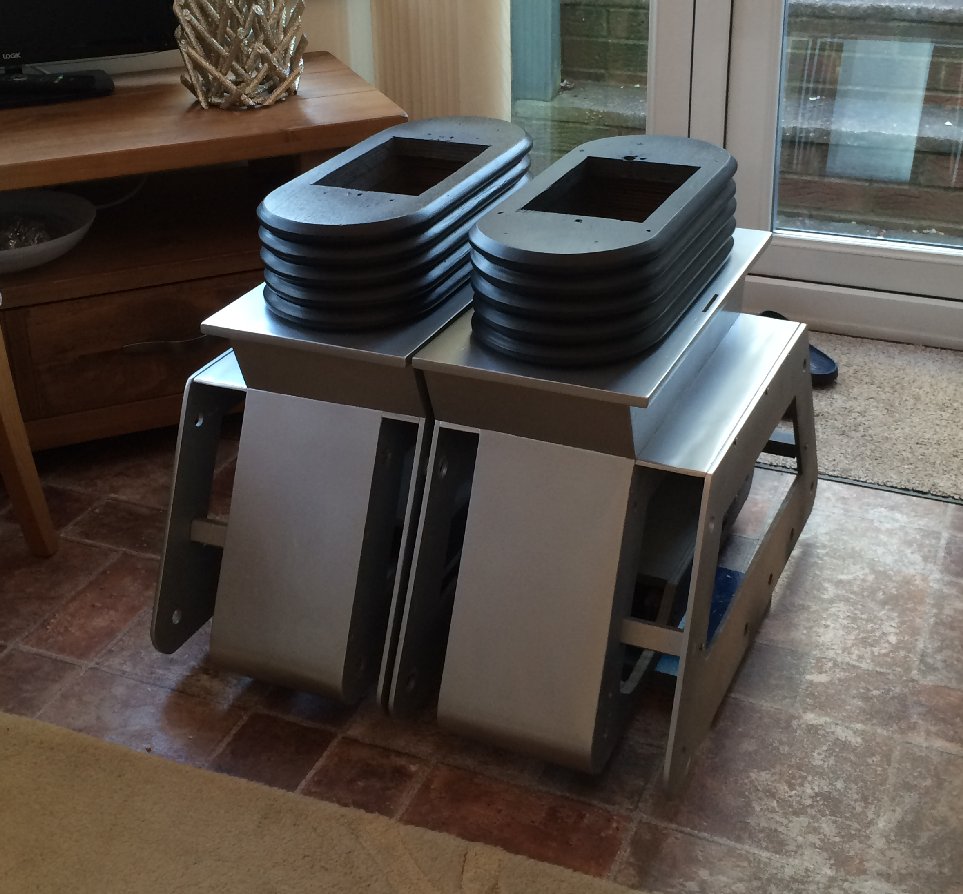
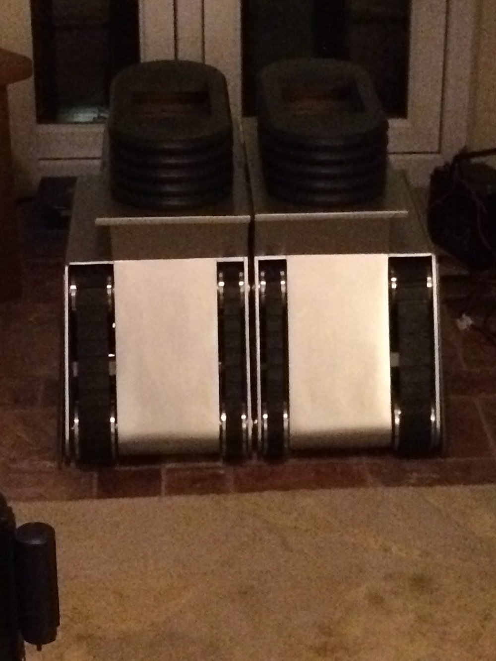
I have
blown 2, 1 at 18inch diameter & 1 at 17inch diameter, and
yes they are circular too!!.
Here
are the pictures plus my thanks have to go to my neighbour Craig
who supplied his large oven again.
Plus
my other neighbour Alan (Cole) who made the compressed air box
and the input regulator valve from an old bicycle inner tube.
He also supplied the air compressor.
I will
be blowing some more next week which should complete this part
of the project I have learned a lot from this experience and have
really enjoyed it.
Hope
you like the pictures - Paul
05/30/2006
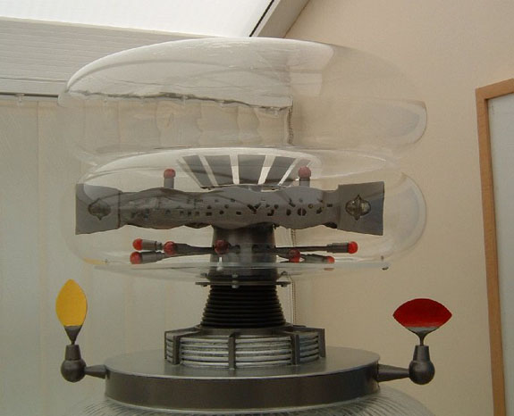
Motorized Ears & Additional Info
Firstly Thanks
again Scott for these great ears I have at long last installed
them and motorised them.
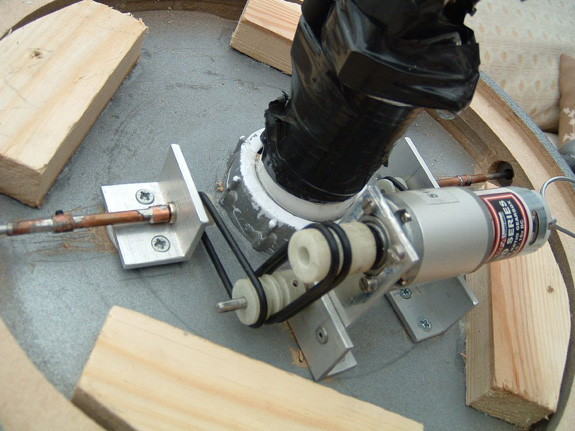
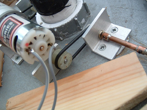
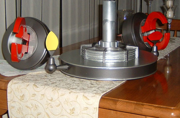
Here
are some pictures of my drive assembly; it consists of O rings
and nylon pulleys made on my neighbour’s small table top
lathe.
I did
start out with elastic bands but the O rings worked much better.
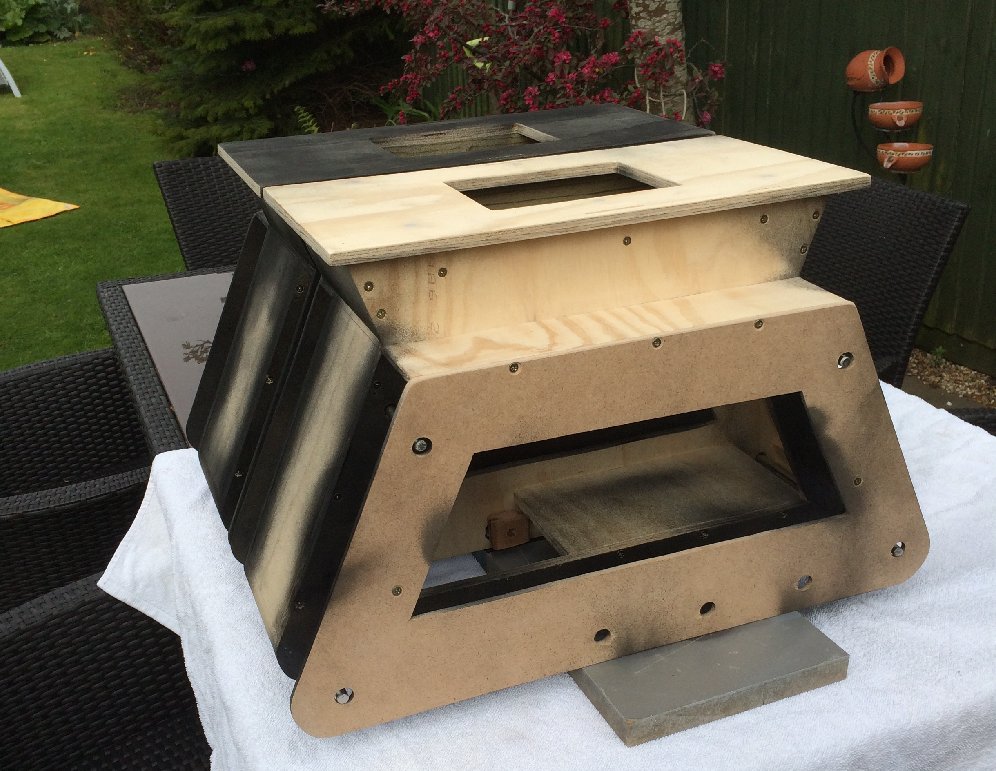
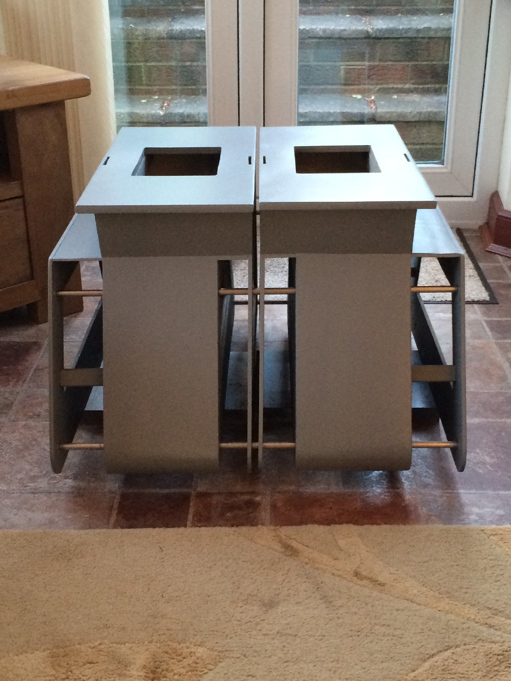
I have
1 final update in progress – a new Bubble created with compressed
air with a whole new system I have created
Hopefully
I can make it this time – I have had some good advice from
some people from a helicopter manufacturing company (Westland
Helicopters they make the Apache)
Some
Info on my B9 Setup
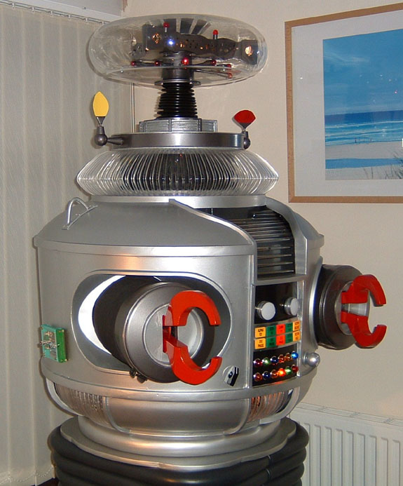
The 12 teeth/belly
lights are the ones from Allied Electronics from the club site
under parts then under off the shelf and my bulbs are 12volt,
my Torso motor is in here too , I infact have 3 of these in my
B9 , 1 for the Brain 1 for the Ears and the 1 for the Torso. To
get the 2 patters was a complete fluke;
The light controllers I have in my B9 are from a company here
called Maplins (www.maplins.co.uk)
The light controllers have 10 channels and have 2 buttons, 1 for
the light pattern and 1 to switch the lights on & off
There is also a rotary switch to change the speed. I have 2 bulbs
in parallel on each channel I used 8 channels 6 for the teeth
and 2 for the big chest lights all my lights in the torso are
12volts.
I have now updated the bottom row and they run in the opposite
direction to the top row so it’s a bit like the car KITT
from Night Rider.
The treadsection motors – I managed to find a local wheelchair
repair centre and just by chance the chap there was getting rid
of an old obsolete electric wheelchair it had 24volt motors with
the shaft set at 90degress offset to the motor body.
I tried and tried to use my rubber treads to drive my B9 but I
couldn’t get it to work as I would like so I copied the
layout of a small radio controlled Dalek.
I used the front 7 ½ inch diameter wheels from the wheelchair
and attached them to the motor shafts then I mounted the motors
as seen in my scrapbook. I decided to set it up so the wheel is
¼ inch lower than the treads to the ground to reduce the
drag then the rear of the tread section rests on the ground and
the belts rotate as if they are driving. The raised ¼ inch
does not show especially when my B9 is on carpet.
The batteries inside my B9 are 12volts and the motors (24volts)
are only running 50% when I have him moving flat out which is
about the same speed as he moves on the TV. Plus the motors are
never under any real load
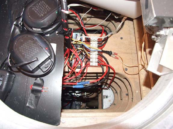
With
the radio control I used a 4 channel system with 3 speed controllers
1 for the motor that drives the torso via the lazy susan. And
the other 2 drive the tread motors. When I asked for help from
my local radio control shop I realized the B9 is setup like an
R/C Tank. Left and right motors forwards and reverse for mobility
then the torso rotates like a tank gun turret.

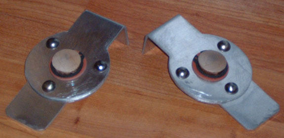
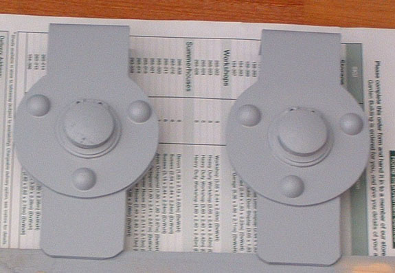
04/04/2006
I would like
to say Thankyou to Craig for his sensor instructions – I
used them again.
And
I have a new set nearly ready for fitting, picture below.
Plus
here’s a picture of my new neck from Vince in place also
nearly forgot I just made the new light box for my.
Chest
bezel here’s a picture of that too.

03/27/2006
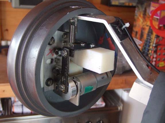
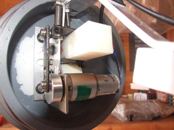
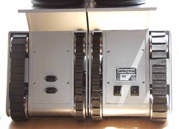
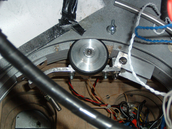
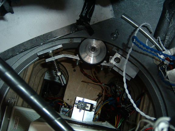
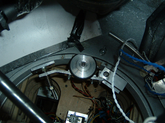
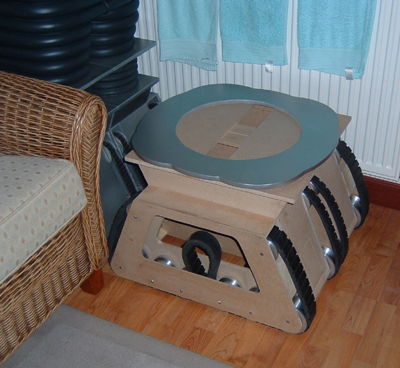
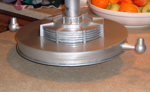
To motorise
the treads I had to rethink my method here are some pictures.
I used 2 wheelchair motors 24volt 6amp but by using 12volt input
the B9 runs slower and is easier to control.
I also
enclose a couple of pictures of my torso motor – the same
as I used in the brain but with a spring loaded bracket to alter
tension etc.
With
regard to the radio control the torso motor is just the servo
pushing and pulling a switch to switch the motor on and of in
forwards and reverse, plus my two tread motors are controlled
by speed controllers.
Here are a
couple of movies:
B9001.WMV
B9002a.WMV


01/13/2006
Motorized
Tread Section Upgrade.
I have
the motors ready to install in the new treadsections and I now
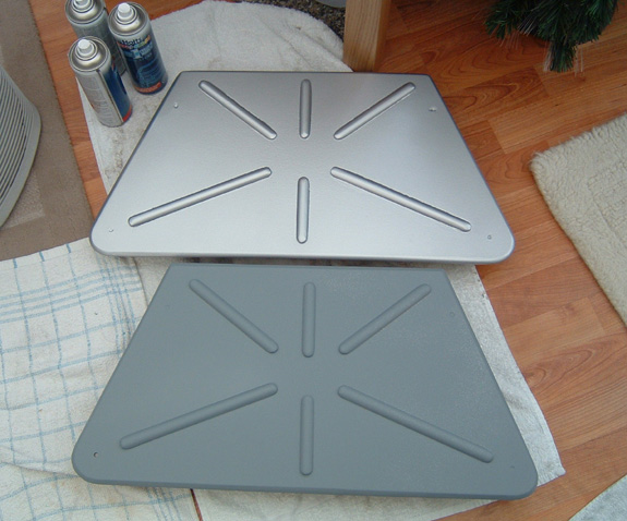
have a new waistplate too. I
will fit the waistplate when I install the lazy susan cover.
Here
are a couple of pictures of my new parts.
2005
10/11/2005
I have some
picture updates of my B9 taken today, it’s the last ones
before the radio control upgrade.
I have
had one of the pictures made into icing and it has been put onto
a birthday cake for me this Thursday, I will be 44 (oh the pain!)
Hopefully by
Halloween my B9 will walk rotate (left and right) and talk!

09/09/2005
Hello All
I have
been very busy lately and apologise for being out of touch.
However
I have made a new MDF donut and I have a set of rubber treads
and aluminium wheels nearly finished including full remote control
of my treads and full automation of my torso for rotation.
The
torso will rotate 90degrees left and 90 degrees right.
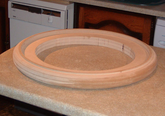
The Donut
work was extensive initially I asked Mike J for dimensions which
worked out great thanks Mike!
My friend
Alan told me to get 4 pieces of 12mm MDF which I purchased, then
he stuck the four together and cut out the circles for me, and
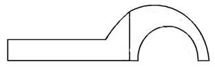
then he used his router to cut the .88 radius for the donut
Then
I had the job of priming filling and painting etc.
Enclosed
are my progress pictures the priming wet and dry and filling was
a case of doing this 4 or 5 times but I am happy with my new donut
and will be fitting next week the priming etc took 1 week.
In 2 weeks
time I’ll be upgrading the tread section so I’ll be
sending some pictures etc then.
Paul
06/15/2005
Hello All,
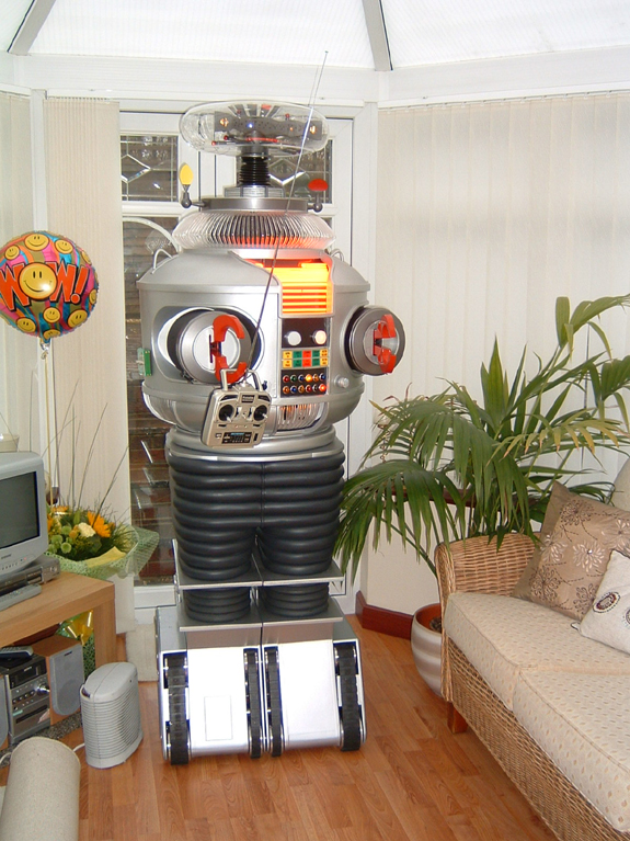
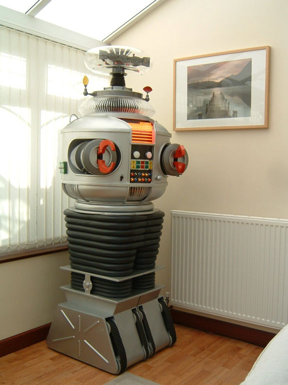
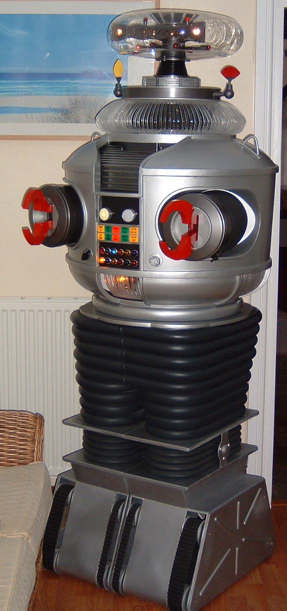
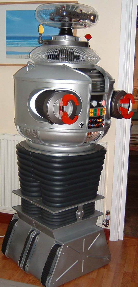
Here are the pics of the completed B9 with his powerpack in place. Hope
you like the pictures.
Paul


06/14/2005
Here are 5 pictures of my powerpack complete with the decals I
am really pleased with it and now I have to drill the 3 holes
in the Torso.
I’ll
let you know how it works when I have it installed.
Thanks
again Mark for all your help it really is appreciated!
Paul

06/02/2005
Hello Everyone
I have fitted
the new collar to my B9 and at the same time raised the Bubble
to give the same look as in the TV series.
(or as close as I can get).
Plus here are some sneak preview pictures of my Powerpack courtesy
of Mark Wees instructions and the Ppack board he gave me.
I couldn’t get all the original components but I am pleased
with the pack.
All I have left to do is to install the decals which are being
printed at the moment plus I have to install the copper/brass
Pins
into the 20pin connector which I made from one piece of nylon
and I used a hot screwdriver to make the 20 indents.
When
I have the powerpack fitted I will send an updated set of pictures
of my B9 complete (with his Powerpack!!)
Paul
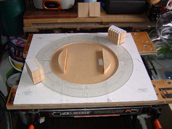
05/20/2005
Hello All,
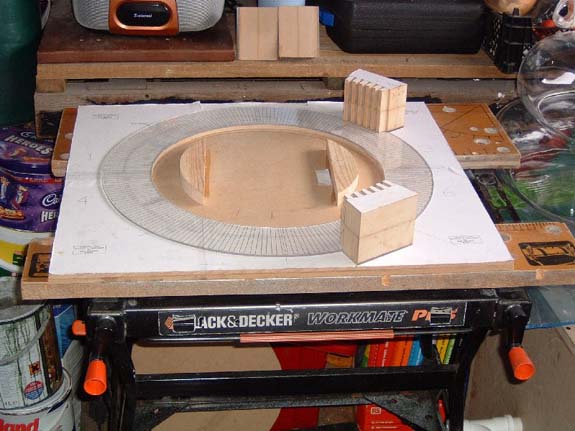
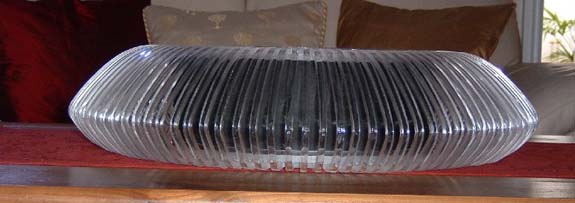
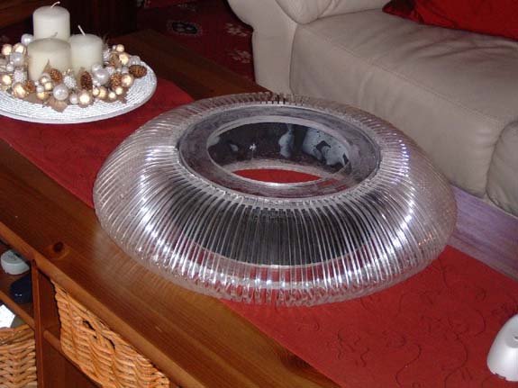
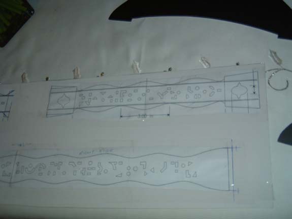
Here are the pictures of my collar setup I used Bob G’s
6 page layout for this. I put a 3mm piece of acrylic
on top of the layout to give the ribs a good flat surface. As
I made a cylinder in the centre of the collar this time I put
2 locating pieces of wood to centralise the cylinder. The
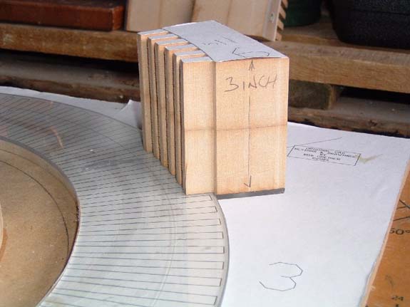
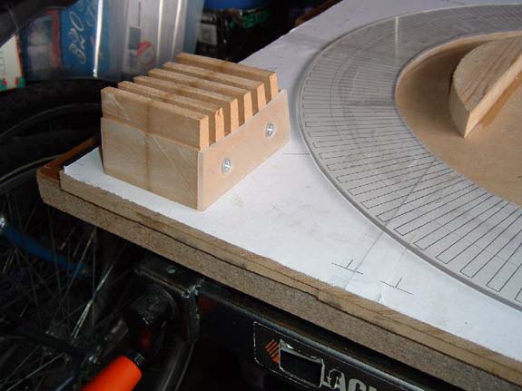
jigs my friend Alan made included a piece of the 3mm to enable
to jig to locate up to the edge. To make to jigs Alan
took a piece of the layout glued it to a piece of MDF and cut
out for 5 ribs on the bandsaw. We discovered
the jigs with the short rib holders worked as the longer ones
would not slide back away once. The ribs were in place.
Alan has to take most of the credit here as he provided all the
wood cut out and made all my jigs including the rib one. Alan
has been a great help to me on my B9 Project. As you
can now see my finished collar looks much more like the real thing. My
2 local helpers have been great and have also taught me some new
skills they are:
Alan Cole from above in this email.
Pete Davidge, my neighbour, he made many bits for my B9 plus he
soldered my 2 light control boards from the kits I bought. Pete
also made the frame on my power pack which is in progress right
now he said he wanted to take a look at my instructions from Mark
(Wees) and came back over to me later in the day with the frame(brass)
soldered together.
I owe
both these guys a lot!!
Paul


05/18/2005
Hello
Everyone,
Here
is a small movie of my B9, my daughter Lucy enabled him to move!!
Paul
Click here to download or play
Windows Media Clip -B9.wmv
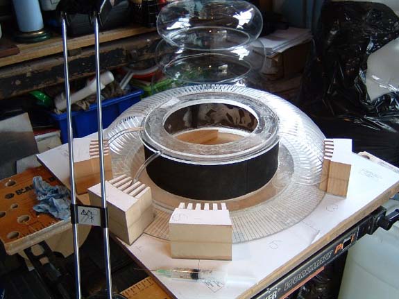
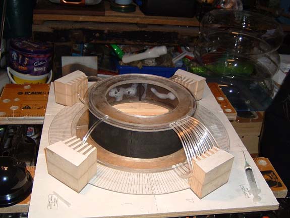
05/15/2005
Hello All
Here
are some pictures of my new Collar.
I used Bob’s Layout again and have glued it to a piece of
MDF then glued an acrylic disk over the top.
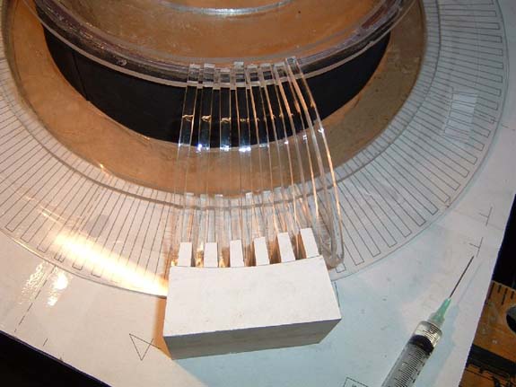
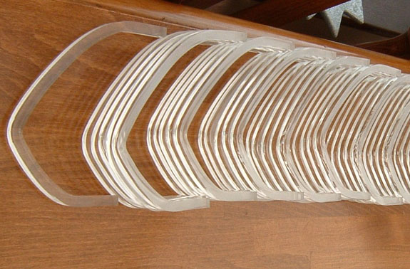
I have
dry installed all the ribs so they are not evenly spaced.
However
my friend Alan is making a jig to hold 5-10 ribs so I can glue
them and ensure they are all parallel.
I will
send pictures when I have the jig so you can all see as it may
help others.
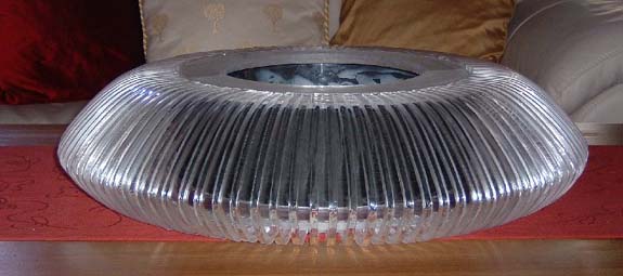
The
pictures enclosed today are the collar with the 108 ribs dry fitted
plus some of the collar chassis with its shroud in place.
I decided
to have an acrylic cylinder inside the collar to strengthen it.
The shroud is glued to the cylinder.
I put
my recent bubble with it just to check it with the collar size.
I’ll
keep you all up to date with the powerpack too.
Paul
05/13/2005
Hello Everyone
I have been upgrading my collar on my B9 as my first upgrade.
I was never happy with the way I built it so I have rebuilt the
jig and have remade the 108 ribs
I put a piece of clear acrylic on top of the jig and all the ribs
are flat and straight.
The failings of my first collar were down to me not being patient
enough – Bob’s plans however were super as I reused
them again I have enclosed 2 pictures of the formed ribs as you
can see they look correct this time. I’ll
send a picture of the completed collar.
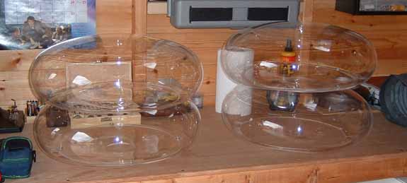
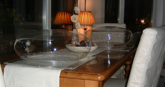
Bubbles
I have been able to make 2 new Bubbles one was 16½ the
other however is 18”!
I have also enclosed my bubble box and some assorted pictures
of all the bubbles etc.
I still cannot get it 100% round but it is nearly there and I
cannot notice the slight off round when the bubbles are installed.
In the picture of the 3 stacked bubbles the top is 16½
the middle one is 18 and the bottom one is 19½.
I am
also working on a powerpack too – Mark Wees very kindly
sent me a circuit board and a set of detailed instructions.
Which
I am very grateful for. I’ll let you know how the
Ppack comes out.
Paul


04/22/2005
Hello Everyone
Now
I have completed the build of my B9 I would like to thank you
all for making this possible for me:
Mike
Joyce – for making the B9 builders club available and for
the superb Torso, Torso Switch, the
personal Dick Tufeld CD and many hours of helpful tips and guidance.
Mark Thompson
– Mark got me started with the whole bottom half of my B9
from the Treads to the donut. Plus Mark gave me a set
of eye lenses for the brain.
Bob Greiner
– With Bob’s help and guidance plus his excellent
website I was able to make the Radar, Collar, Torso Vents and
Knee hinges.
Craig Reinbrecht
– Craig has helped me with the chest bezel the programming
bay Neon Wiring and the sensors plus the ear posts plus many drawings
of the braincup with the cam etc Craig sent me a diagram of the
wrists from which my friend was able to make a set of Aluminium
ones! Plus many hours of help and guidance with building
my B9.
Dave Painter
– Dave sent me a diagram for the Brain, braincup, crown,
and brain rods. From this I was able to make the components
plus a claw diagram which enabled me to make a set.
Dennis Wilbur
– Dennis sent me my Neon and Torso hooks – plus a
diagram from the B9 helpers of the dialights from which I was
able to make a set! Plus
again many hours of advice and guidance.
Between you
all I was sent many additional diagrams and information that has
become invaluable for me in the build process. Thank
you All again I really have appreciated everything.
Thank you
ALL for all your help and support and I will be asking more questions
when I start Phase Two...
I will
take a break before I get into the real robotics!!
I've
also enclosed a shot of him just before I started to re-assemble
him. From an extremely happy B9 Builder, I hope you have
a good weekend.
Paul
04/21/2005
Hello Everyone
I have made the knee hinges for my B9 (Thanks again Bob (G) your
website gave me all the info to build these!!)
Here are the pictures.(I only photographed one set as the others
are being made right now.)
Assembled, primed & finally painted ready to fit – I
will be fitting them Friday Night.
As soon as they are fitted I will take some full size photos of
my B9 and send them over, this will be phase one of my B9 completed.
Thanks
again to ALL of you for all your help over the last year without
all your help I wouldn’t be anywhere near where I am with
my B9.
Paul
04/06/2005
Hello Everyone
Here
are my most recent pictures of my B9 I just have the knee hinges
and a slight mod to the neon Backplate to do.
Hope
you are all well.
Paul
04/03/2005
Hello Everyone
I feel
as if I am on the home stretch with phase one of my B9 –
just the knee hinges to make & fit now.
I have
however just started on my replacement collar as I wasn’t
completely happy with my first attempt.
This
will be the first part of phase two.
Just
like to you all to see these updated pictures, I have completed
the brain, braincup & crown plus I have installed the motor
for the crown and the brain rods. My Torso knob controls
the speed of the lights plus my programming bay has four switches,
2 to switch the lights on and off & 2 to change the sequence.
I have four as I have two light control boards installed,
one for the brain and one for the lights in the main body (Dialights
and the 12 belly lights).
Have
a good weekend all of you.
Paul

03/17/2005
Hello Everyone
Just
a quick note to say I have completed my B9 Brain, However this
was only possible by Mark (Thompson) as he sent me a set of Lenses
which fit great.
I would
also like to thank Dave (Painter) for the original brain drawing
as without this I would have no brain; (this sounds a bit like
a quote from the Wizard of Oz!!)
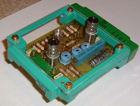
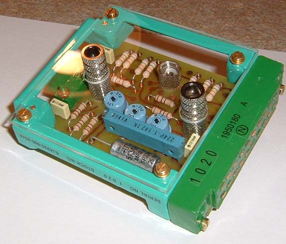
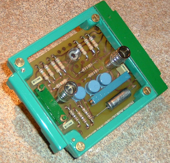
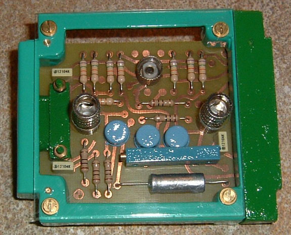
In the
5th picture the circuit board is a light control board I already
have one of these controlling the torso lights , in my programming
panel you can see 2 black buttons on the right hand side one of
these control the light sequence and the other toggles the lights
on and off.
I hope
you all have a great weekend
Paul
02/28/2005
Just an update
really as I am building the brain at the moment I am using Mike
Lowen’s instructions from his website but I made the brain
from 3mm acrylic and the surrounds are made of Foamex which is
the same as sheet styrene. As
you can see I have some cutting out to do!!
I have included
some pictures of my B9 as I have already made the brain cup and
light rods plus the crown. When this is complete I will
have another go at a perfect bubble. My box has been upgraded
so I can test again next week. I also have the knee hinges
to make and I am using Bob G’s for this as his instructions
are great.
Paul


02/15/2005
Hello Everyone
I have been
seriously researching how to make the bubble for my B9.
I was able initially to make a 16inch one but have been able to
make two further ones.
One
is 17 ¾ and the other is 18 ¼.
Unfortunately
I couldn’t get the bubble completely round it did go slightly
oval on one side which I have put at the back.
The
other small problem is the fact I used wood for my dish inside
the vacuforming box and when the wood heats up the grain starts
to raise and imprints into the top of the bubble, it is very slight
but I can see it if I look closely.
However
if I look at the bubble straight on it looks fine.
Here
are a couple of pictures.
The
bigger bubble is the one without the lights in(bubble…)
as I am building the brain at the moment.
Paul
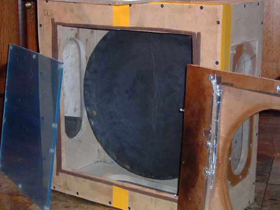
02/04/2005
I am currently
researching how to make a bubble for my B9 and have read the article
from TerryM on the B9helpers. I spoke to my father in law
who is a carpenter and he made the box – I was able to get
an 18inch dish made from wood as per the instructions. I
have however used a few pieces of ¼ inch acrylic but have
made some good progress. I had the bubble forming very
well the other night until my vacuforming box lid broke. I
have enclosed some pictures of my 16-17inch bubble, just for effect
I put Xmas lights into it jut to see how it looks. I
will be trying to make the bubble properly over the next week. I
will at some stage buy the Fred Bubble but it would be good for
to have a backup bubble just in case!!
Here
are my Pictures I will let you know how I progress with this.
2004
10/26/2004
Hello everyone
Just a note with some
pictures of my up to date progress.
I have completed
my collar - thanks again to Bob(G) for the info on his
website.
As you can see I have at last started on the B9Creations
Torso (no longer available). All the holes are cut and I have primed it so
I can see where I need to fill, sand etc.
Fortunately, I don't have much work to do as the Torso is excellent.
I would like to thank you ALL as without your help I would have
NO B9.
I am working on the prgramming bay & Torso vents now.
I have a weeks vacation so I am hoping to get as much completed
as possible.
Thanks
again guys I hope you enjoy the pics.
Paul
10/13/2004
Hello
Everyone,
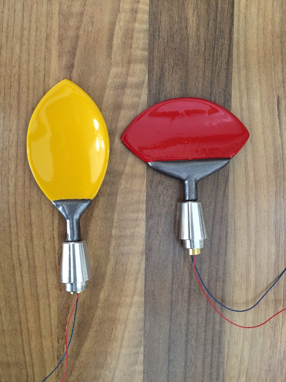
Here
are some pictures of my completed wrists,claws & radar.
I saw Mark's Picture of the 2 colour Radar & have painted
mine the same. You are right Mark, it looks much better.
I have now started the process of the collar.
Paul
10/07/2004
Hello
Everyone
Here
are a couple of Pics of my B9. I have not put the donut
in place as it is ready to go on the finished robot so it is stored
at the moment. I made the side panels from MDF & half
round dowels. I studied my 2nd season DVD to get the angles etc
as close as I could. I have however today painted the Radar
in the two colors, I will send a photo later. So here is
the current progress, next job building the collar, then to the
torso!!
Paul
09/27/2004
Hello
Everyone
Please
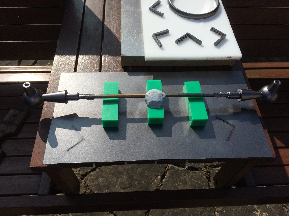
find below my finished Radar.
I decided to take BobG's advice and improve the 1 3/4 band around
the radar.
I was able to obtain an aluminium strip which i attached.
I have a photo of the Radar re primed and one of the completed
I also made the sensors using Craig's info from the club (Thanks
Craig)
I couldn't follow all the instructions but was a ble to make the
sensors
and mount them on the epoxy putty that goes as hard as stone after
a couple of hours
I sanded this and painted.
Next time i will try and make the complete ones!!
I have
my MikeJ Torso (thanks Mike)
That is my next big task !!
Paul
09/20/2004
Hello
Everyone
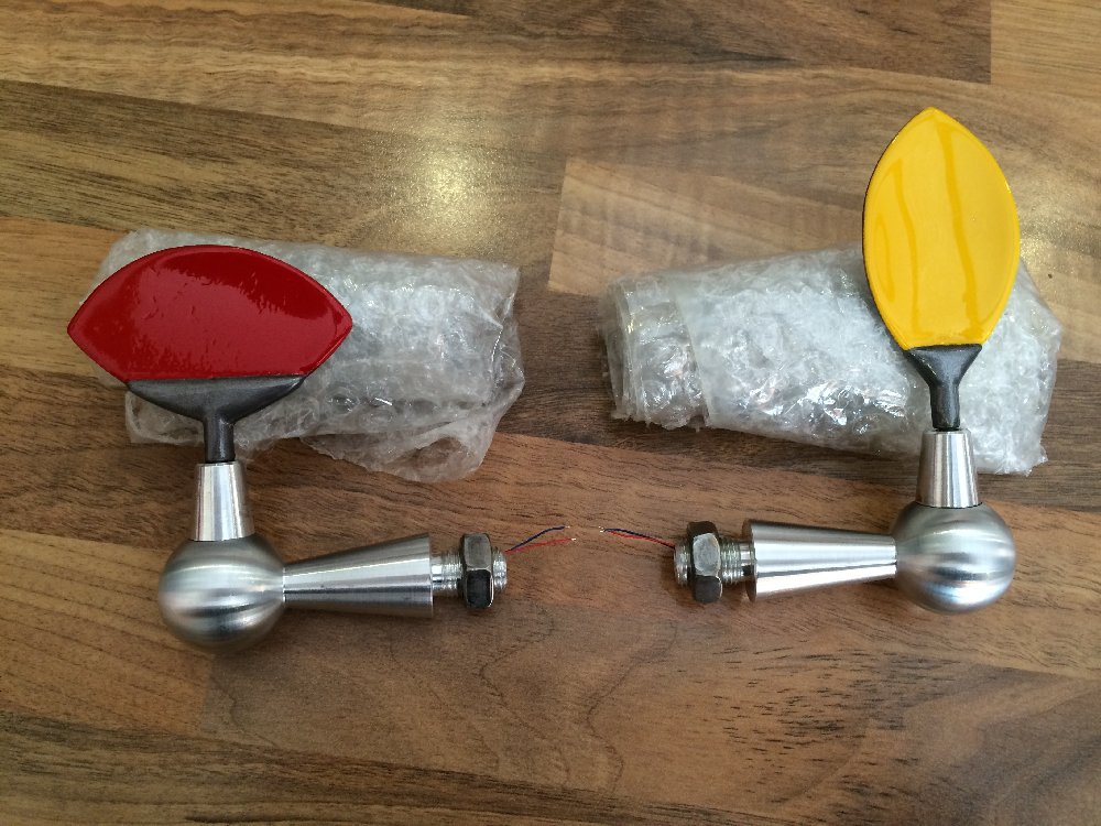
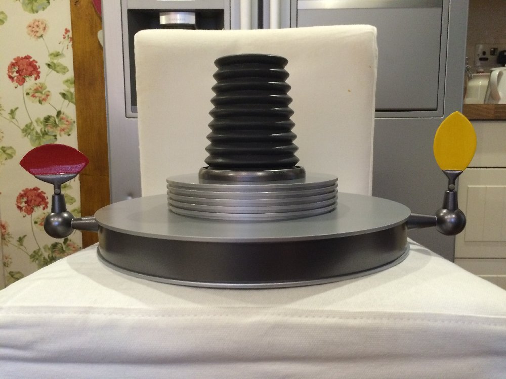
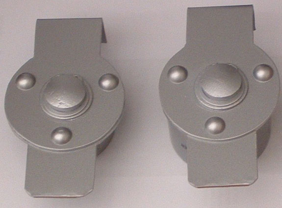
Below
are photos of my Radar, it just needs its final coat of paint
when I assemble my B9.
I must take this opportunity the thank Bob
G. for the instructions as without these I would have no Radar!!!
As
you can all see the ears are slightly narrow at the sensor end
but as i have no lathe and had to use my drill as a turning device,
it was the best I could do as an initial go. The rest of
the ears are a wooden ball from a craft shop and a wooden flowerpot
from the same shop with the top lip cut off (the ball is 1.25
inch diam) and the flowerpot is .75 of an inch. I used
the diagram so kindly sent from Craig R. the drawing was from
Dave(P) so thanks again to Craig & Dave.
Thanks
again to all of you for your help, guidance & advice etc.
I will keep you all up to date with the project as it develops.
Paul


 Paul
F . ( B9-0203 )
Paul
F . ( B9-0203 )