Previous
Entry Top Next
Entry
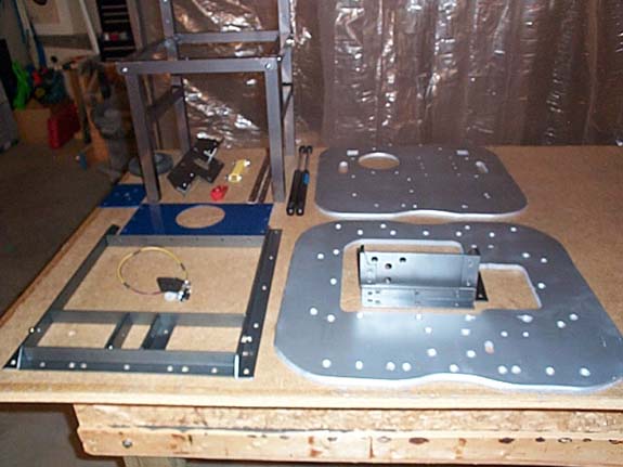
11/06/2004 - Fabrication and assembly of the leg support
mechanism
Here's
a shot of all the components for the leg support mechanism.
The
Leg Support Frame
Blueprints
for the Frame
Side
Supports cut from Norm's welded leg supports.
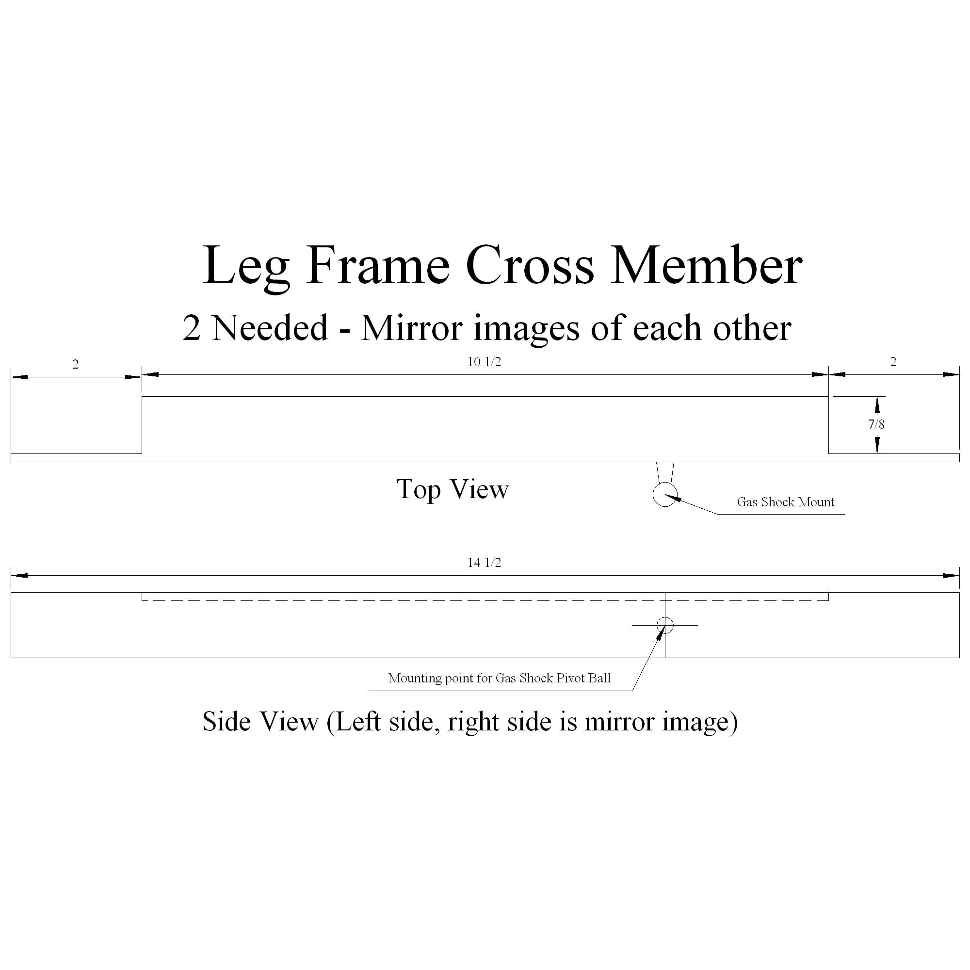
Leg
Frame cross members - Gas Strut pivot points.
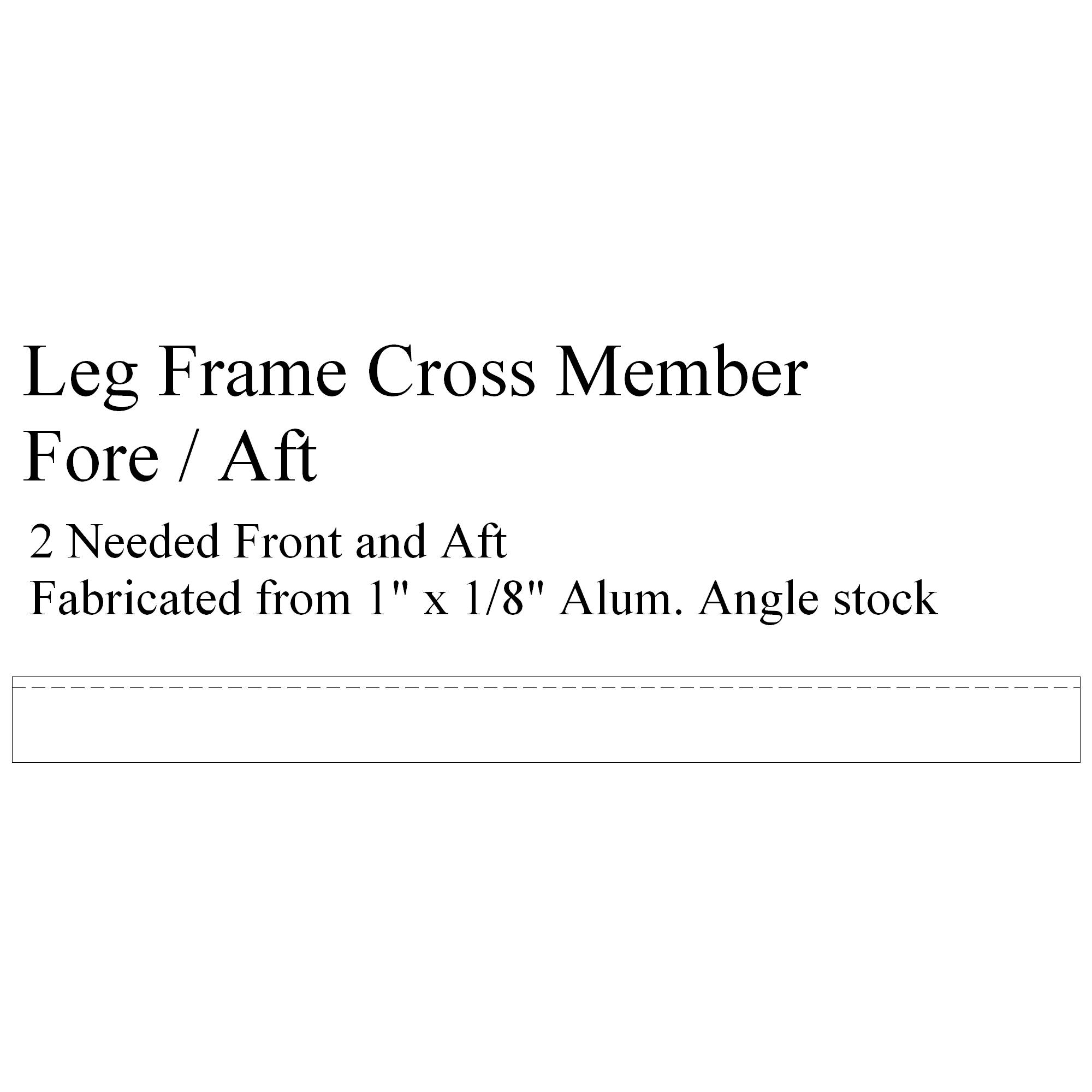
Leg
Frame Fore/Aft cross members.
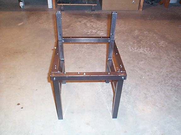
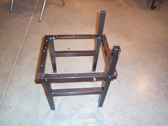
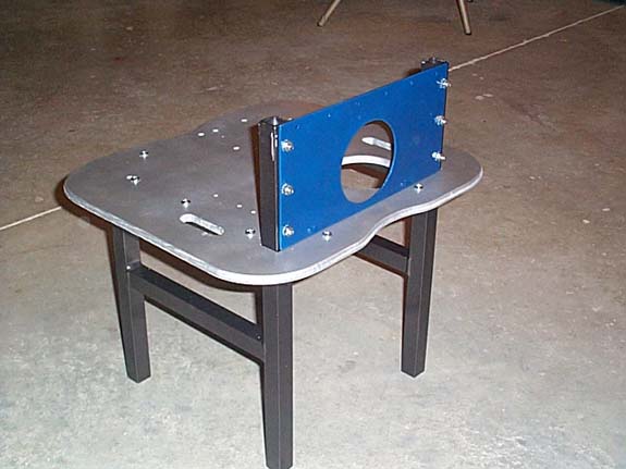
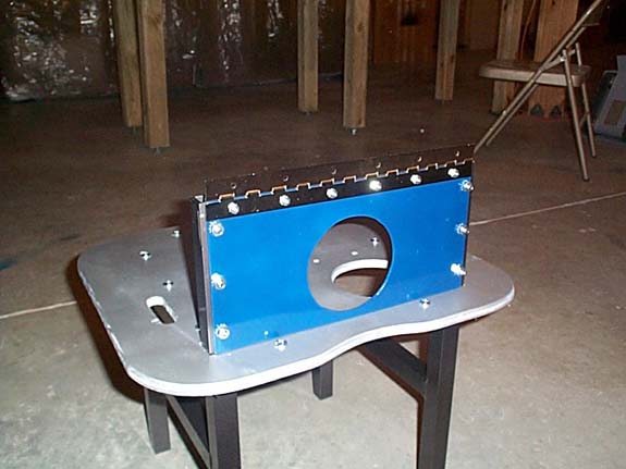
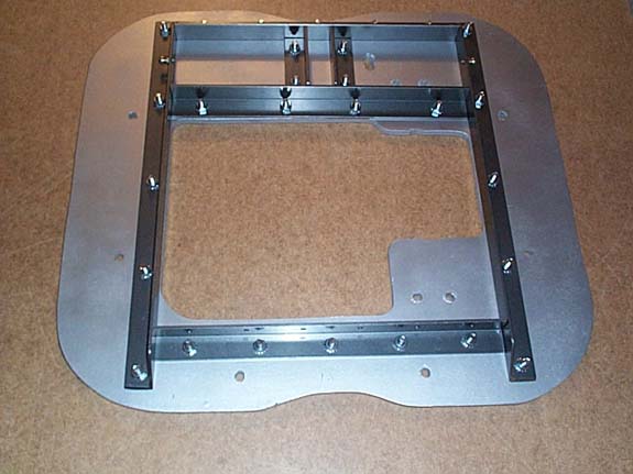
Here
are a few shots of the assembled Leg Support Frame:
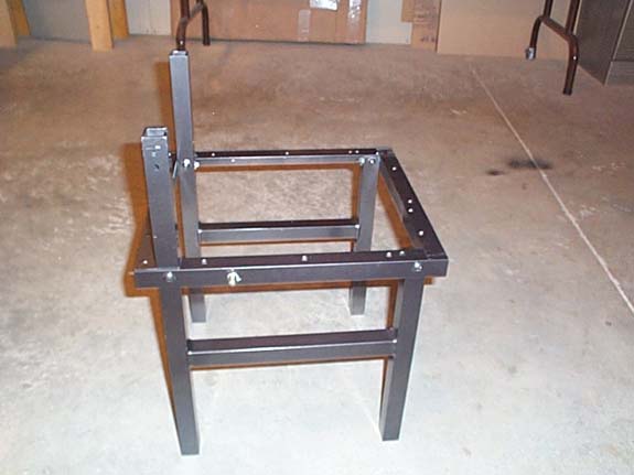
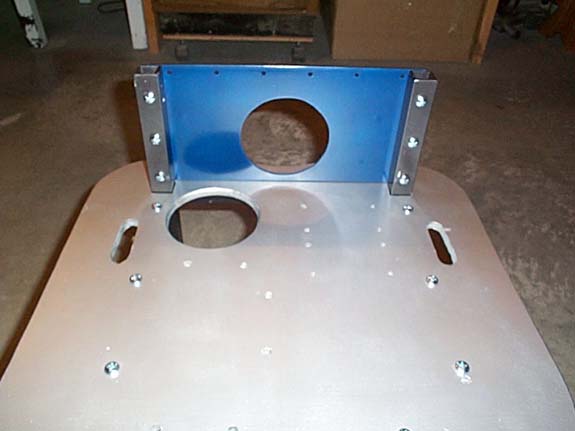
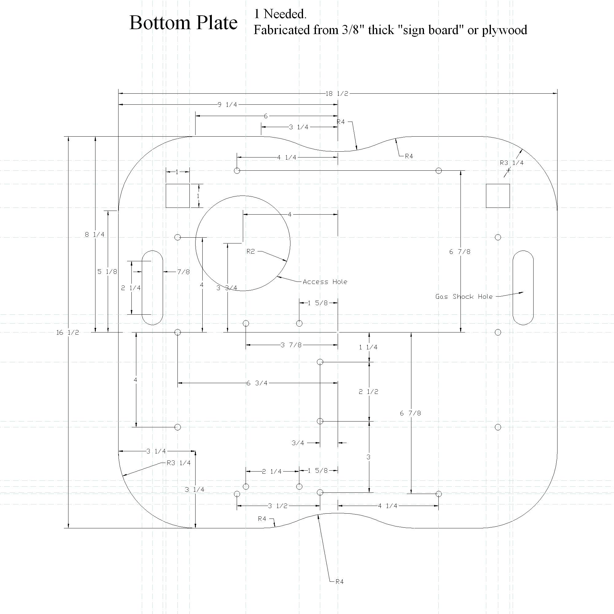
The
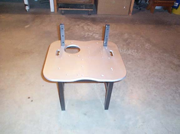
Leg Support Bottom Plate
The
bottom plate provides an attach point for the hip motor and the
leg section electronics.
Blueprints
for the Bottom Plate:
Bottom
Plate.
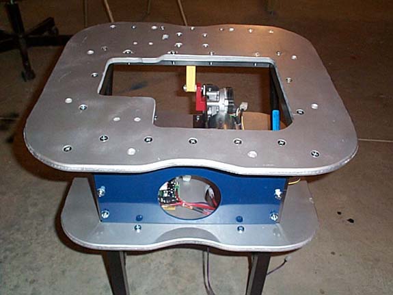
Here's
a shot of the bottom plate in position:
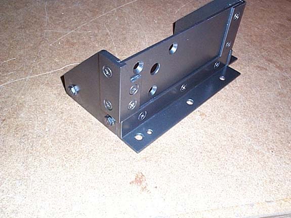
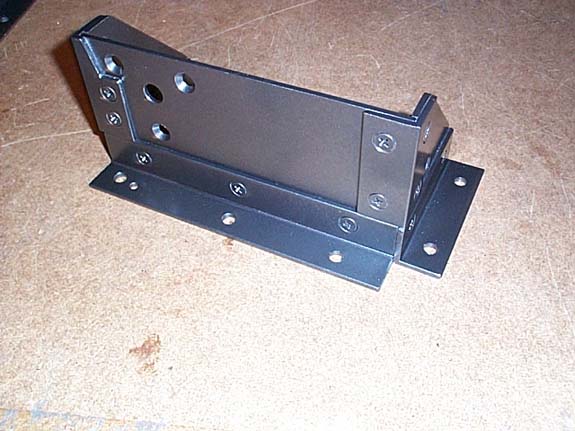
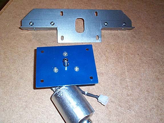
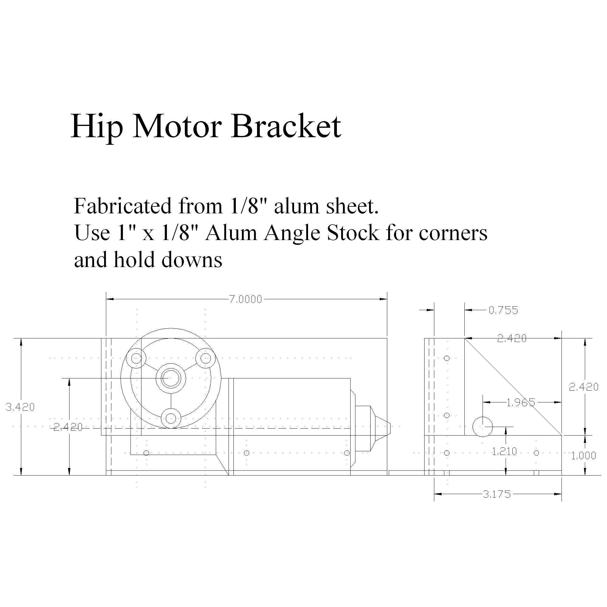
The
Hip Motor Bracket
Blueprints
for the Hip Motor Bracket:
Hip
Motor Bracket.
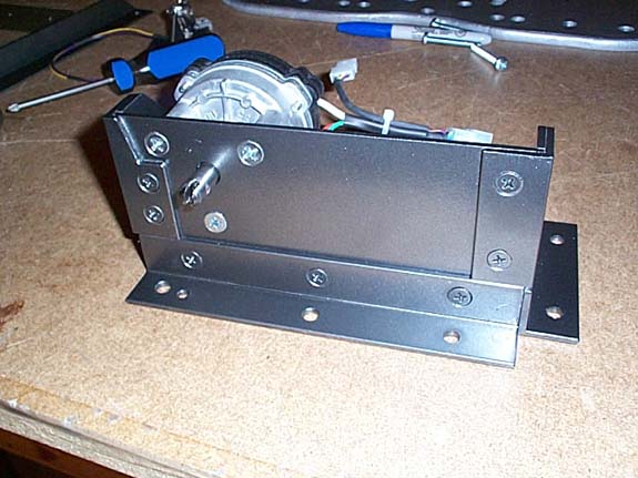
A
few shots of the motor bracket:
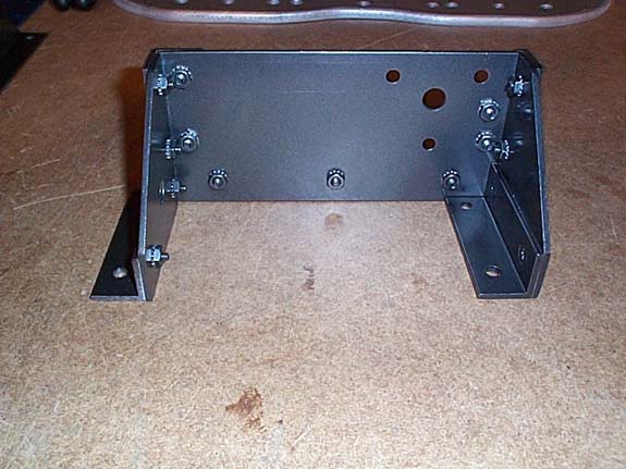
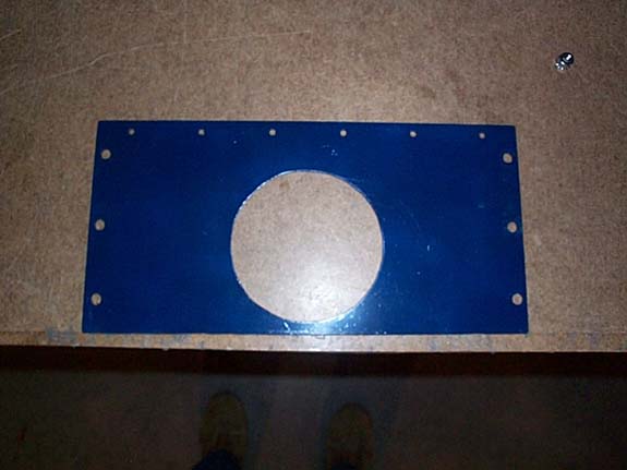
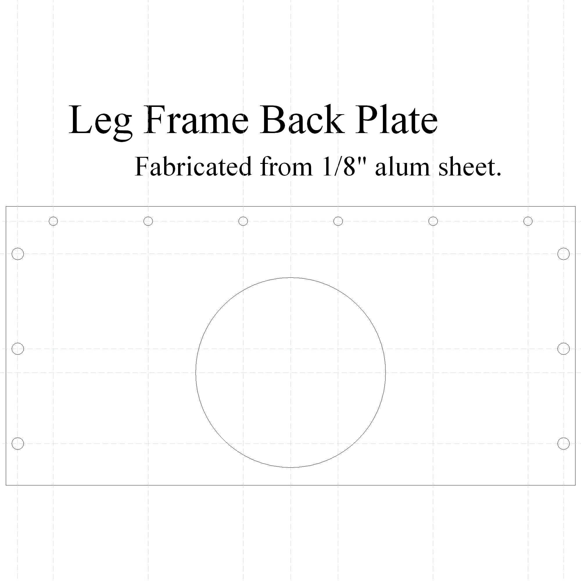
The
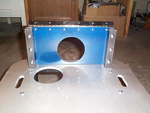
Leg Frame Back Plate
The
back plate helps hold the support's "square" and provides
an attach point for the 12" hinge.
Blueprints
for the Back Plate:
Back
Plate.
Here
are a few shots of the back plate:
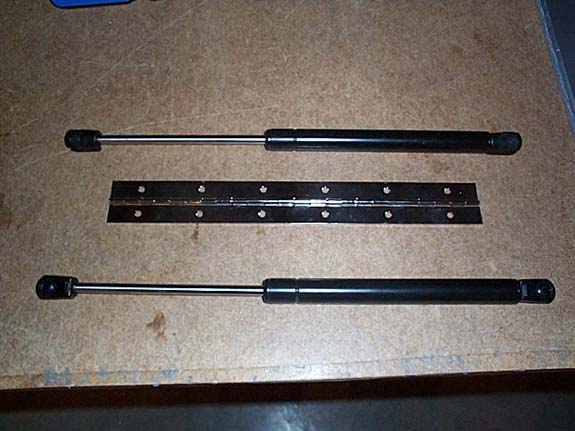
The
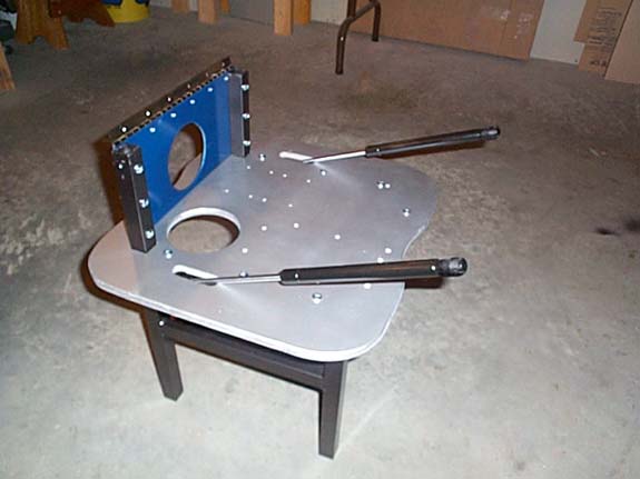
Hip Hinges and Gas Shock Struts
The
Hip hinge is just a 12" hinge that I picked up at a local
hardware store.
The
Gas Struts hold most of the weight of the torso. This allows the
hip motor to raise and lower without excessive loads.
Part
Numbers for the "Strong Arm" struts: NAPA 819 -5245
CarQuest 4419
Part
Numbers for the "Strong Arm" struts are no longer valid as of 5/9/15.
New part number that can be used in this build
would be : 4517.
Best deal is at AutoZone at time of this writing.
AutoZone cross referenced the Strong Arm part number to the following: SG359009
Information on the strut itself:
Stabilus
Lift-O-Mat
USA - Gastonia, NC 28052
3824LG 0230N 213/14 C27
Above infromation thanks to Greg Logue.
Here's
a shot of the struts and the hinge:
Hinge
in position.
Struts
in position:
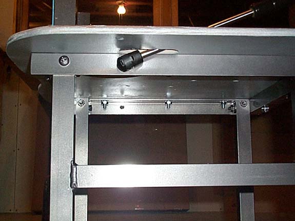
Motor
attached to Hip Bracket:
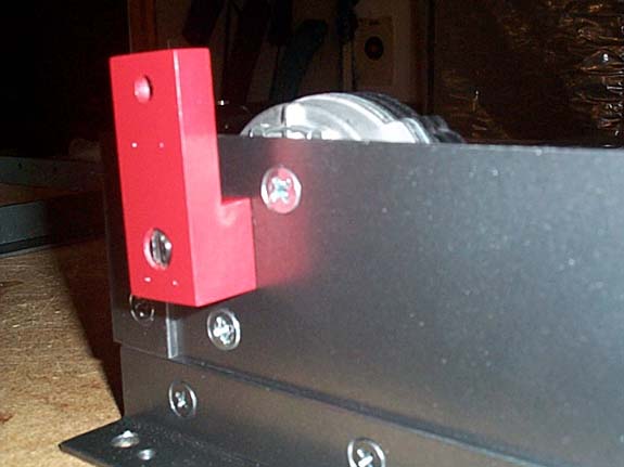
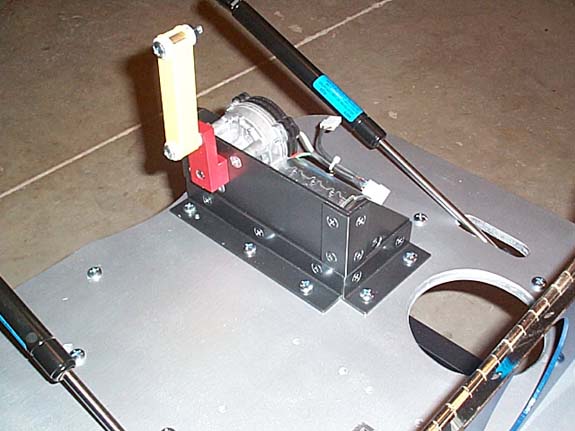
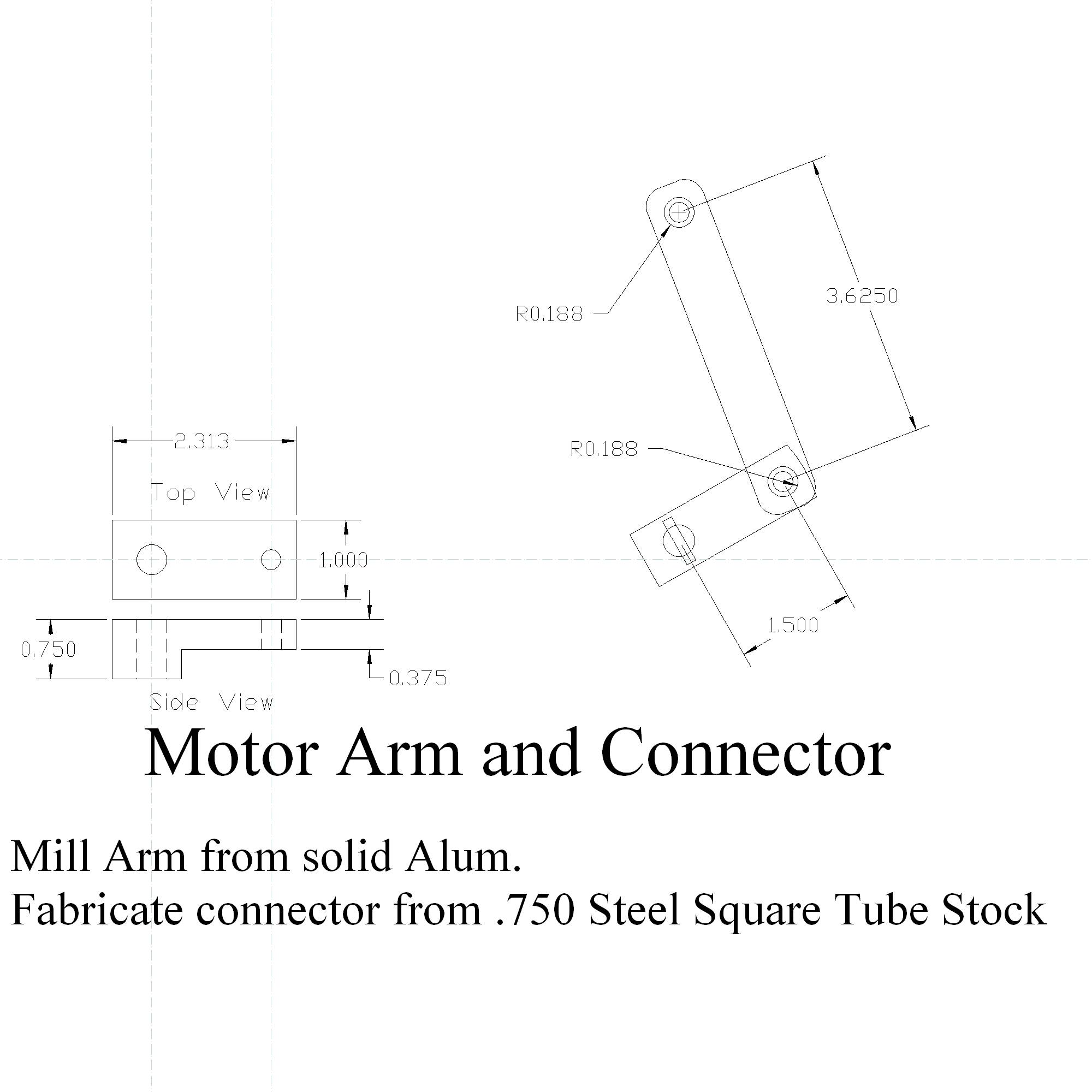
The
Hip Actuator Arm and Connector Rod
The
arm (red) and rod (yellow) allow the motor to raise and lower
the front of the hinged sub waist plate. This allows the Robot
to lean forward and backwards.
Blueprints
for the Arm & Connector:
Arm
& Connector.
Here
are a few shots of the arm & connector parts:
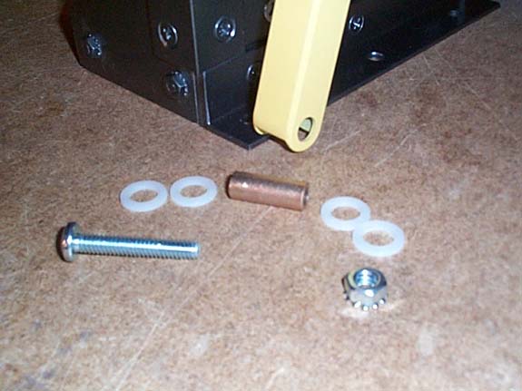
A
brass bushing and nylon spacers for the linkage.
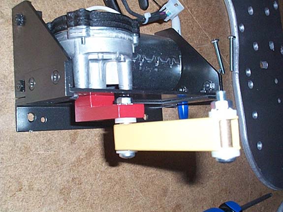
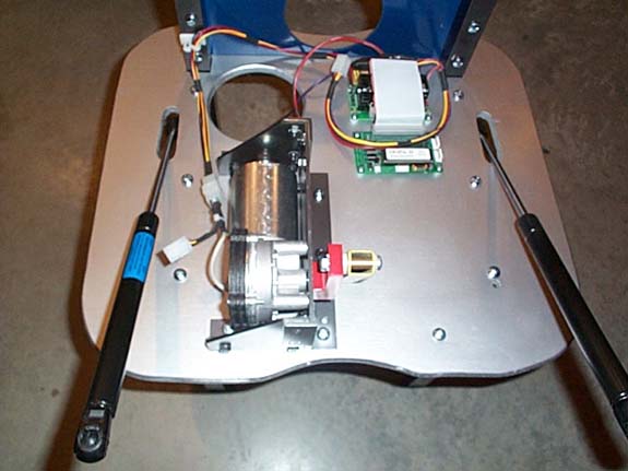
Mounted
to the lower plate:
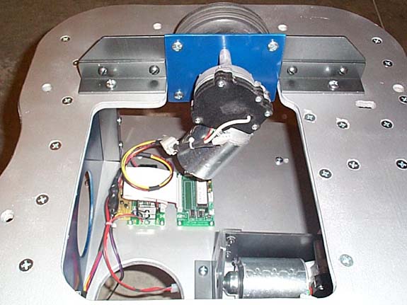
OOPic
and Motor Controller assembly mounted to the lower plate:
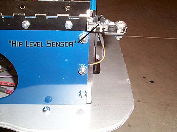
Optical
switch to detect if the Hip is above or below "level":
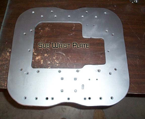
The
Sub Waist Plate
The
sub waist plate leans forward and back and provides a mounting
location for the torso rotation motor.
Blueprints
for the Plate:
Sub
Waist Plate.
Here
are a shot of the sub waist plate:
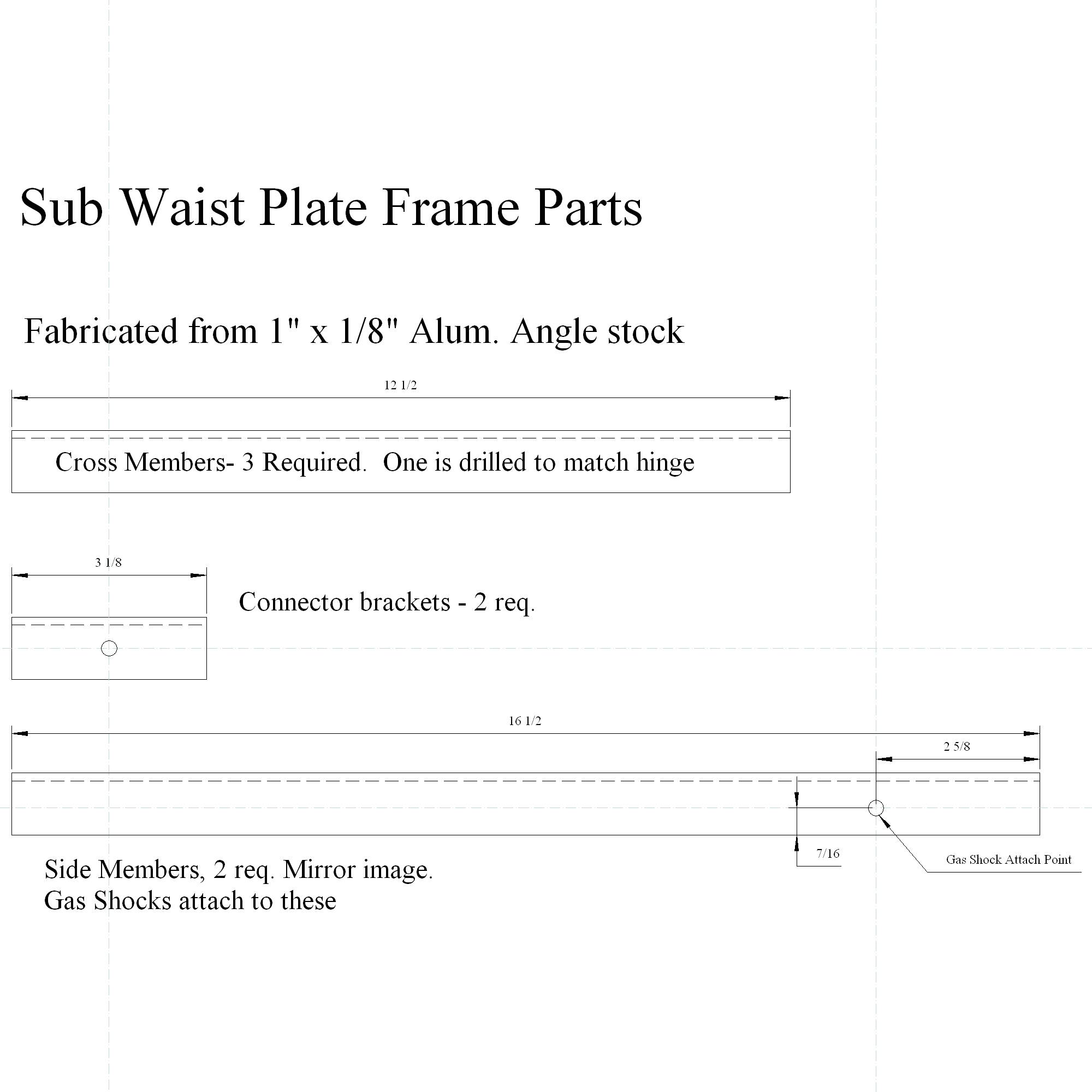
The
Sub Waist Plate Frame
The
sub waist frame provides strength and attach points for the gas
shock struts.
Blueprints
for the Frame:
Sub
Waist Plate Frame.
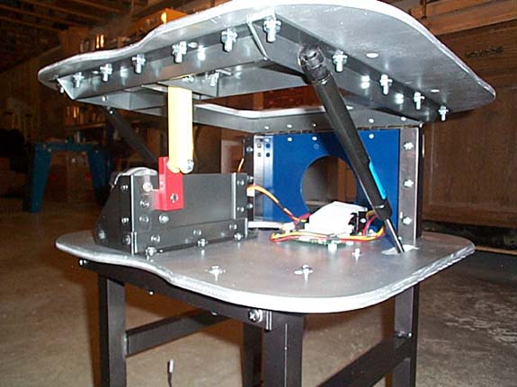
Here
is a shot of the sub waist plate frame attached to the sub waist
plate underside:
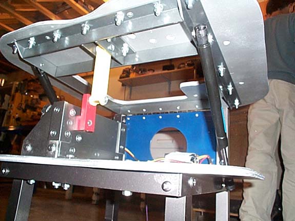
Here's
the assembly attached to hinge and gas struts, with a little help
from my son!

Here's
the connector arm and rod attached to the frame:
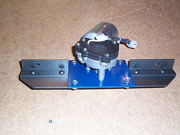
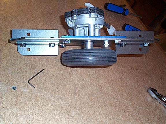
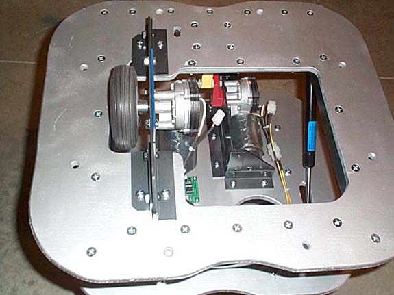
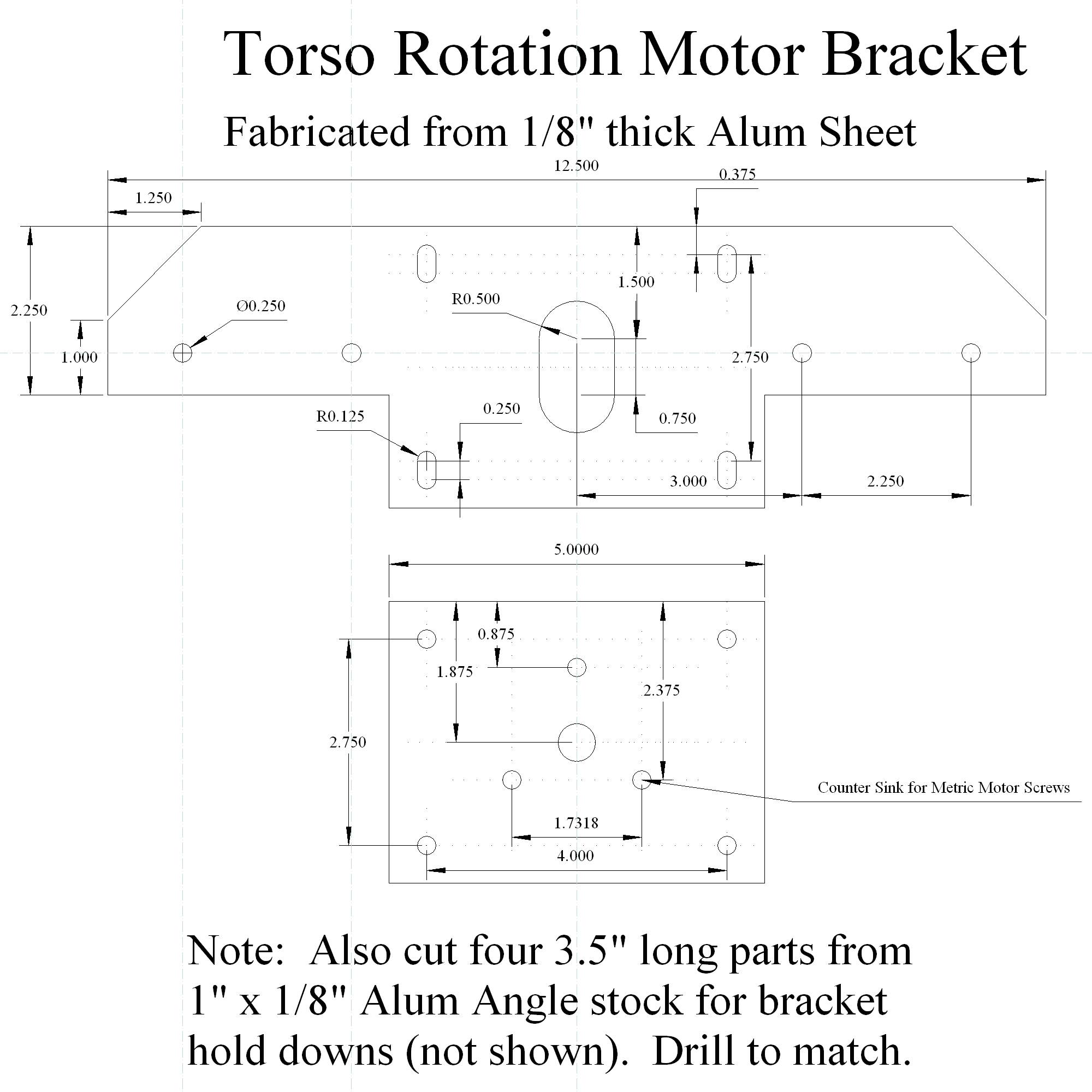
The
Torso Rotation Motor Assembly
A
Bracket holds the motor and allows for vertical adjustment of
the wheel. The wheel is a 4.5" diameter hobby
wheel meant for large model RC Aircraft.
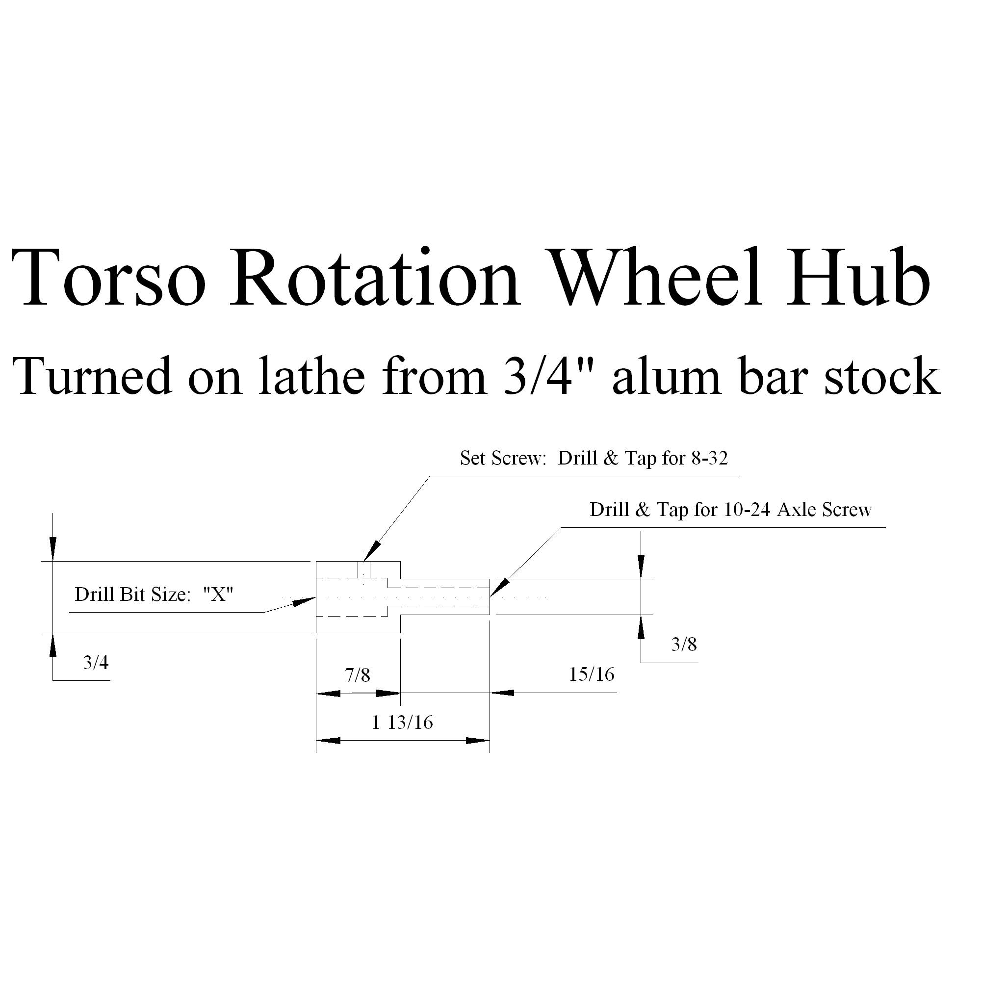
Blueprints
for the Bracket and Wheel hub:
Bracket.
Hub.
Here
are some shots showing how it all goes together:
Here
it is attached to the sub waist plate:
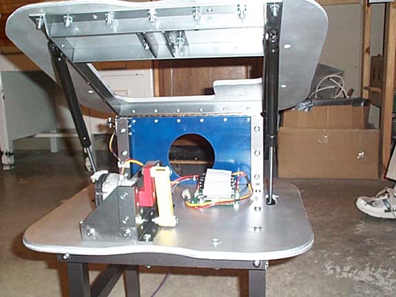
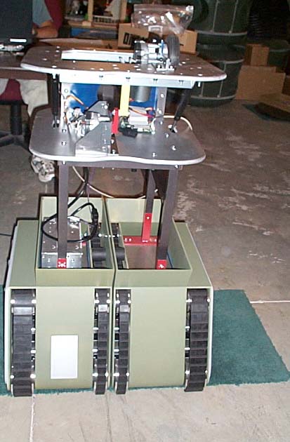
Here's
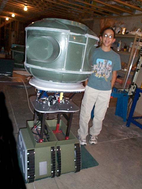
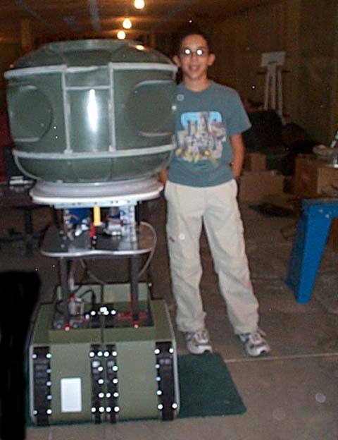
the whole thing in place on the Treads:
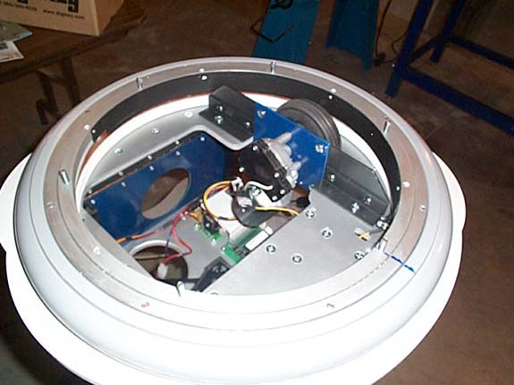
The
Donut/Waist Plate assembly, attached to the sub waist plate:
Matthew
shows off the suports with the torso in place:
Testing
everything, hip motion, torso rotation and soil sampler control.
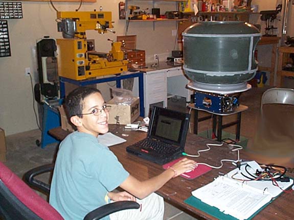
Fun
Stuff!!
Previous
Entry Top Next
Entry


 Mike
J. ( B9-0002 )
Mike
J. ( B9-0002 )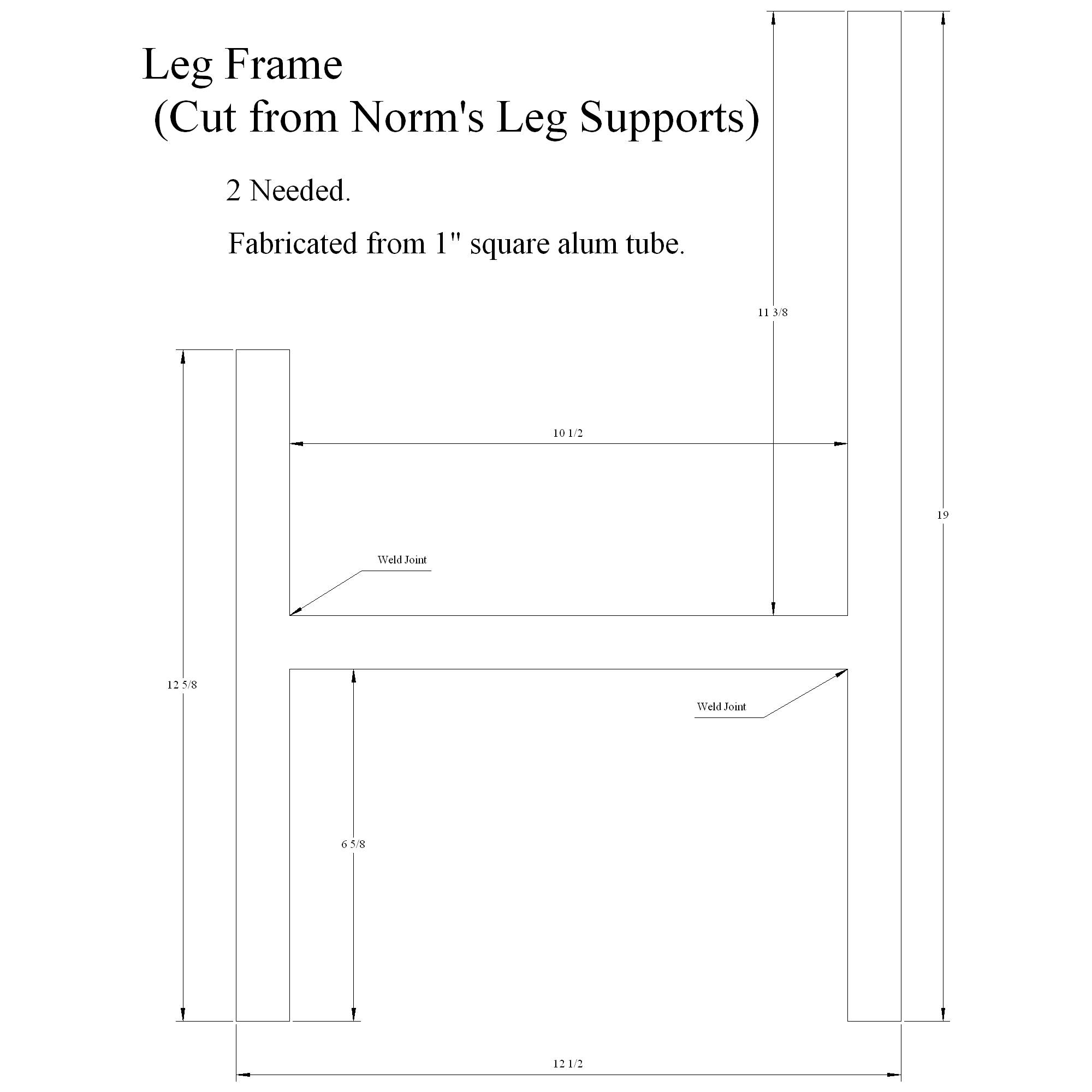