Previous
Entry Top Next
Entry
10/05/2004 - Homemade Motor Shaft Encoders
WARNING!
This topic is not for the technically faint of heart! It
really only applies to folks that plan to use some kind of computer
control of motor functions. With that said, I will
describe what I'm doing as best I can but some knowledge of
micro-controllers, quadrant encoders, etc. is assumed. Tons
of info on these topics can be found by searching the internet,
your library, etc.
The
Problem
It's all fine and dandy to talk about a computer controlling
a motor but in reality several things have to happen to do it
correctly. To start with, you have to have some way to
control the motor's speed and direction. Since I'm
using the OOPicII as my
micro-controller Magnevation's
Motor-Controller seemed like an easy solution. OK,
that solves the control problem. Now for the hard
part. How does the OOPic keep track of the position of
the moving part? I'll illustrate this problem with
an example.
Torso
Rotation
Mechanically I have a motor with a wheel on the shaft. As
the wheel turns it contacts the CSS plate causing the entire
CSS and torso to rotate. With my Magenvation Motor-Controller
the OOPic can be programmed to rotate the torso left or right
at different speeds. BUT, it has no idea which direction
the torso is facing at any given moment. I have decided
to solve this problem using two sensors. First, a
simple "on/off" sensor will detect if the torso is
turned toward the left or right hemisphere (more on that in
a later update). Second, I will use a homemade quadrant
shaft encoder for the motor. In simple terms, the
shaft encoder will allow the OOPic to keep track of the rotation
of the motor shaft by counting (either up or down depending
upon the direction of the motor) every time the shaft turns
5 degrees. The OOPic will use these two sensors to keep
track of the torso position. (The OOPic will reset an internal
counter to zero when it detects the straight ahead position
which is defined as the transition of the left/right sensor
from one hemisphere to the other.)
The
Shaft Encoder
Well, I could buy a nice motor with a built in shaft
encoder, but they can cost hundreds of dollars each
and I need five of them (Hip, Torso, Left Arm, Right Arm &
Bubble lifter). So, it's time to get inventive. The
Dewert motors I used last time worked great and only cost about
$30 each. Also, they have a nice gear box cover that
can be modified to work with my encoder mounting idea. Now
I just need some cheap encoders, so off to Wal*Mart I go. For
less than $10 I found a cheap two button mouse. Now
a mouse just happens to have TWO encoders (x&y axis) built
in, so each mouse yields two encoders for less than $5 each. Here's
a photo of the Mouse I decided to use. It's a Micro Innovations,
Two Button, PS/2 Mouse, Model PD39P.

A
Rough Guide
What follows next is a rough guide showing how
I extracted the encoders from the mouse and mated them to the
Dewert motors. It should be noted that the mounting
is critical! Failure to position the encoder sensor
correctly relative to the encoder disk will result in junk. I
designed special mounting plates based on this specific model
of mouse using CAD software. I had those plates laser
cut from hard ABS plastic. You could try to make
these plates by hand but it would be tough to get them accurate
enough, IMO. The other tricky part of this operation
is drilling and tapping the main motor output shaft. I
used my lathe, drilling it in the exact center without a lathe
is not impossible, but it would be very difficult.
How
To Destroy a Mouse
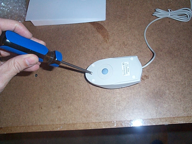
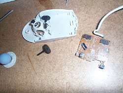
I began by taking the mouse apart. Take out the ball
and remove the single screw.

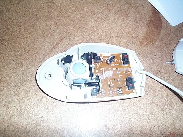
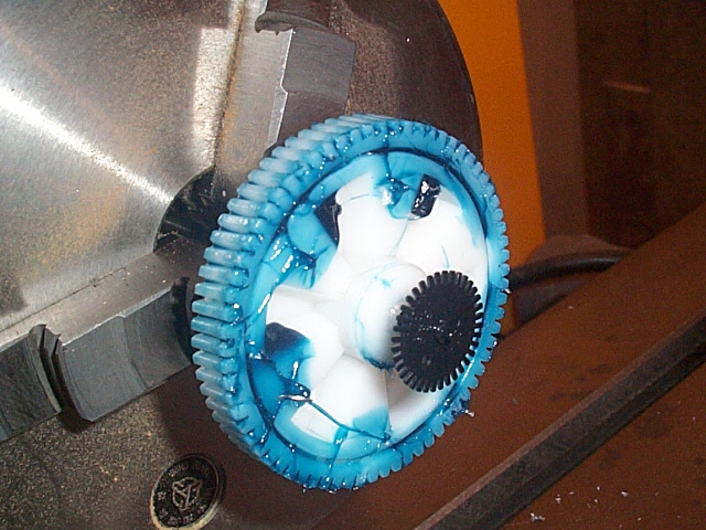
Here's
a shot with the cover off. Note the two encoder disks
and the two encoder sensors. Each encoder sensor consists
of an IR LED and a pair of IR sensors in a tiny black package.
The pair of sensors are slightly offset such that, as the encoder
disk rotates, each one turns on/off out of phase with the other. This
allows one to be used as a counter and the other to be used
as a direction indicator, in other words, a quadrant encoder. (The
OOPicII has code that handles Quadrant
encoders.)

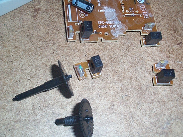
Here's
a shot of the mouse components with the circuit board removed
as well as one of the encoder disks removed.
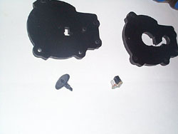
Here's
a "before/after" shot of the complete circuit board
which also shows two encoder sensors that I cut off another
circuit board. Also shown is an encoder disk I just
removed and another that I have modified by cutting off a portion
of the shaft and then cutting 8-32 threads.

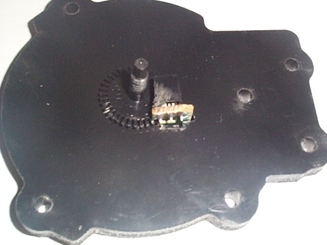
Here
are the two laser cut encoder mounting plates along with the
sensor and disk. The plates are specific to the sensors
and won't work with other mice, but here are the blueprints
(dxf format) in case they help you. ( Top
Base
)
Close-up
of the top cover with the sensor and the disk.

Close-up
of the top cover with the disk and sensor in place.

Close-up
with the bottom plate in place. These photos are just
to illustrate how the cover holds the encoder in the correct
position.

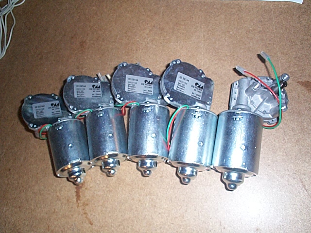
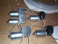
A
shot of the five Dewert motors prior to modification.

How
to order Dewert Motors:
General
sales number: 301-228-3315 Steve W. Rose (Sales Department
Director)
Very Important
- Start out the conversation telling them that you are with
the the B9 Robot Builder's club and you want to order gear
motors - Part Number 000.002.016
You have
to order them by calling during normal business hours (EST):
(you can not order from their web site)
They are $29.50 each as of Nov. 3rd, 2004 They accept Visa
& MasterCard
Tell them how you want it shipped, UPS Ground, Blue, Red.
Cost of shipping is added to your card depending on quantity/weight
and where/how they're shipped.
Using
a band saw to cut off the four rivet heads to allow removal
of the gearbox cover. Be Careful!
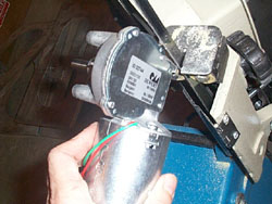
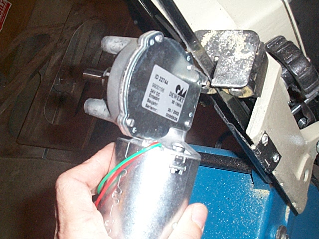
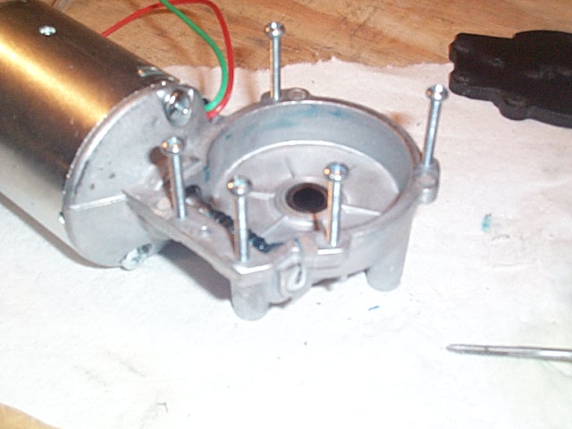
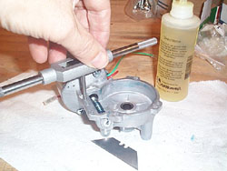
A
shot of the motor after removing the cover. Note the motor,
cover plate, gasket, shaft with gear and washer. Next
we must tap holes in the motor's gear case to allow the cover
and encoder mounting plates to be attached using 6-32 screws. We
must also drill and tap (8-32) the motor shaft on the gear side. The
cover plate will need a hole drilled to allow the encoder disk
to be attached to the motor shaft.
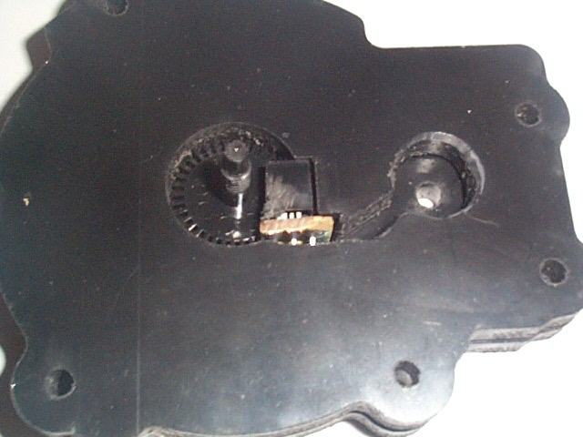
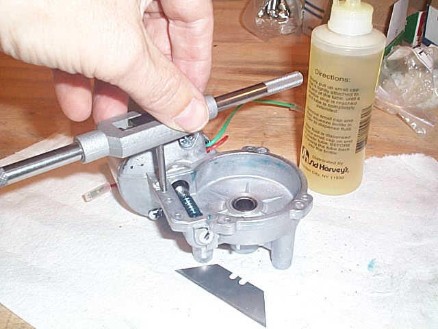
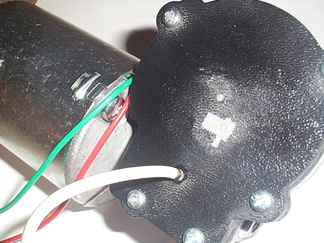
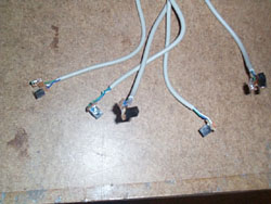
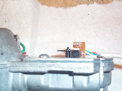
The
mouse cord has four wires, just what we need! I use white
as +5v, green goes to ground (through a resistor!). Orange
& Blue to the sensor outputs. These outputs must
go through transistors before they go to the OOPic. Those
transistors and other components will go on a simple circuit
board which I will talk about later. For now, I just
solder the wires to the sensor like this. (The blue wire is
difficult to see, it's below the white wire.)

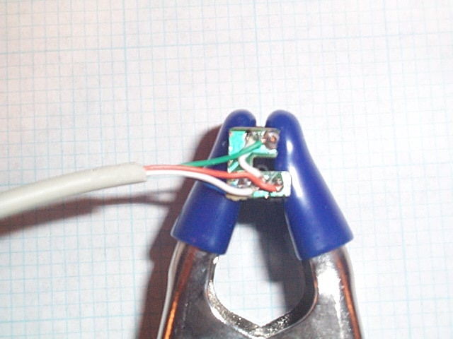
Here
are all five sensors soldered to their cables.
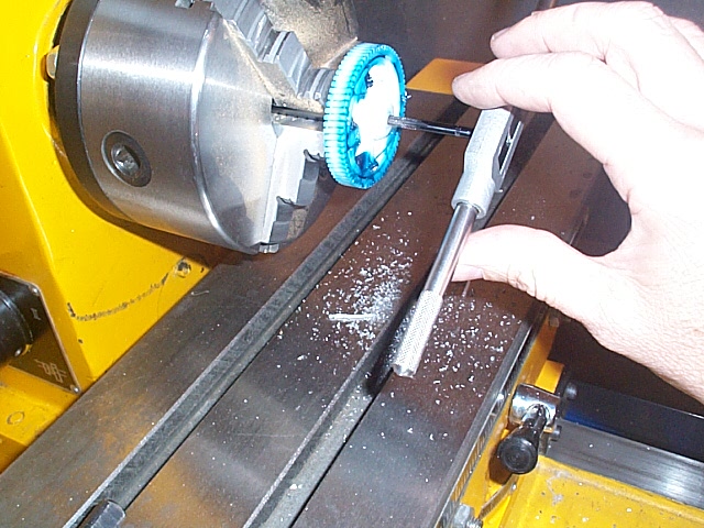
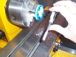
Using
the lathe to drill the hole, for the encoder disk, into the
motor shaft.
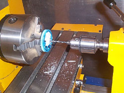
Tapping
the motor shaft hole with an 8-32 tap.
Cutting
8-32 threads onto the encoder disk shaft.

Test
fit - Screwing the encoder disk into the motor shaft.

Tapping
five holes into the gearbox to allow the cover to be attached
with five 6-32 screws. Note that the correct size holes
are already present on the Dewert motor's gear box!
A
shot showing the cover mount screws in the newly tapped holes.

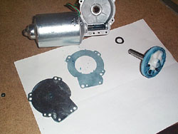
The
Gear and washer have been replaced.

The
gasket is in place and the cover plate and top cover with the
sensor are ready to go.

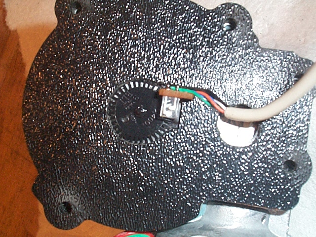
With
the cover plate in place I screw the encoder disk into position.
I used a drop of super glue when I did this to lock it
at the right spot. I use the sensor to determine the correct
spacing (don't want to screw it in too far, or not far enough!).
The
bottom plate is positioned with the sensor in place around the
encoder disk.
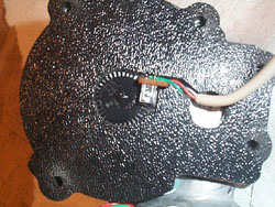
The
top cover is put into position and screwed in place. After
testing to make sure the encoder is working I put some plumber's
epoxy in the opening on the top cover to seal it off.

Here's
a shot of all five motors with encoders attached.
Previous
Entry Top Next
Entry


 Mike
J. ( B9-0002 )
Mike
J. ( B9-0002 )