Star Trek Next Generation Shaker Motor Mod Installation
Let me first say that this is not my mod or my design. One day I was just looking through old RGP posts on Google and I came across this very cool shaker mod for my STTNG. I got the parts together and installed it according to the instructions in that thread and I loved it.
Original concept and design of this shaker mod is by:
Atarijim, Apollo Amusements, Brandon Florida, Apolloamusements.com
This artical, along with pictures were compiled and edited by: David Schulpius, dschulpius@wi.rr.com
What I’m trying to do here is bring it all together with picture instructions to make it easier to make and install. I will quote the author of this design often throughout this article to keep the integrity of the original post. "This is a very simple circuit to construct for about $10 in parts, not including the motor. The effect is a subtle one, as the flashlamps cycled on and off quickly and the motor does not ever come up to full speed. The effect is felt during The Final Frontier, Borg multiball, Q Challenge and Cardassian Encounter, along with the post game show."
The discussion on RGP that I got the idea from is at these two links and can also tell you every thing you need to know to put this thing together and build your own control board:
Google RGP thread #1, Google RGP thread #2
The author and designer of this shaker mod states the following and I share his sentiments:
"PLEASE NOTE: USE THIS INFORMATION AT YOUR OWN RISK AND ONLY ATTEMPT THIS MODIFICATION IF YOU FULLY UNDERSTAND THE CIRCUIT DESIGN AND HAVE COMPETENT SKILLS TO BUILT AND INSTALL IT. I WILL NOT BE LIABLE FOR ANY DAMAGE DONE BY THE USE OR INSTALLATION OF THIS MODIFICATION." Basically according to the above thread by the designer of this mod, this is the stuff you'll need to make this thing work. I've added sources where I found my parts but by the time you read this the components may not be available at that outlet :
Shaker motor -
I bought Shaker motor from Steve Young at PBR www.pbresource.com/ and it cost me about $150 (ouch!). However, I just saw one at Bay Area Amusements for about $90. Please note that this motor shipped with a weight attached on both ends. I removed one of the weights because it was just to heavy and the game would not spin them fast enough to get a good effect. If you want you can re install it after you get the mod installed and working to see for yourself the difference. I'm not sure but perhaps you would run the chance of blowing the fuse if both weights were installed due to increased load on the circuit. Here is the link: www.bayareaamusements.com
Breadboard -
I used a breadboard from a local Radio Shack that had holes with soldering pads. Make sure that the board has holes spaces far enough apart to accept a Molex 0.156" Header . The breadboard is the easiest way to form the circuits but understand the final look is very "hobby shopish"
You will need the following electronic supplies for the Controller Board. I bought them from Ed at Great Plans Electronics at:
www.greatplainselectronics.com/
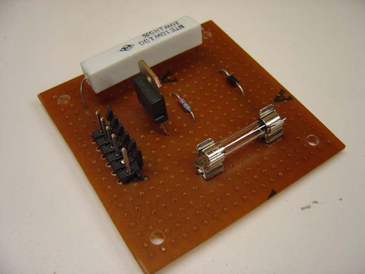
Controller Board Components -
- Fuse and fuse holder - I used two Fuse Clips that solder right to the board, 3AG, High Current and one 2 amp Slo Blo fuse
- One 1n4007 diode,
- One 1 ohm 10 watt resistor,
- One TIP36 transistor
- One 220 ohm 1/4 watt resistor.
Connectors -
"I used the same style connectors used on the WPC power driver pcb to give a clean look and ease of removal for repair for both the input to the breadboard and output to the shaker motor."
These are:
- One Molex 6 pin 0.156" Header
- One Molex 6 hole 0.156" Plug
Wire -
3 pieces of 18 gauge wire about 6 feet in length. You can use the same color coding as the game does; red/white for the +20vdc power, black for ground and blue/violet for the control from Q34/J125, pin 8, (the flashlamps for the shields). I wasn't that picky and used plan red, black and green for ground. Radio shack has this wire in small coils.
>
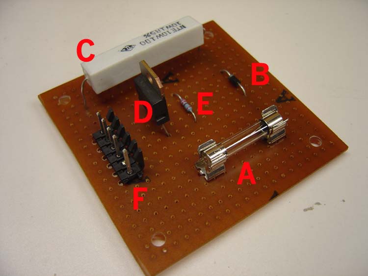
 A - Fuse and fuse holder - I used two Fuse Clips that solder right to the board, 3AG, High Current and one 2 amp Slo Blo fuse
B - One 1n4007 diode,
C - One 1 ohm 10 watt resistor,
D - One TIP36 transistor
E - One 220 ohm 1/4 watt resistor.
F - Molex 6 hole 0.156" header pin
A - Fuse and fuse holder - I used two Fuse Clips that solder right to the board, 3AG, High Current and one 2 amp Slo Blo fuse
B - One 1n4007 diode,
C - One 1 ohm 10 watt resistor,
D - One TIP36 transistor
E - One 220 ohm 1/4 watt resistor.
F - Molex 6 hole 0.156" header pin
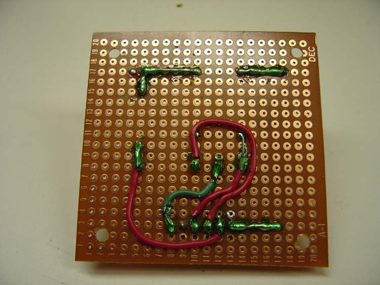
Here's the circuit:
Please note; after making this control board to the specs of the designer I found my shaker motor didn't run. In the original thread is seems that he had the Collector and Emitter of the TIP36 mixed up. If built to those instructions and installed like I did, the motor would not work. Below is the way I wired the transistor to make this board work:
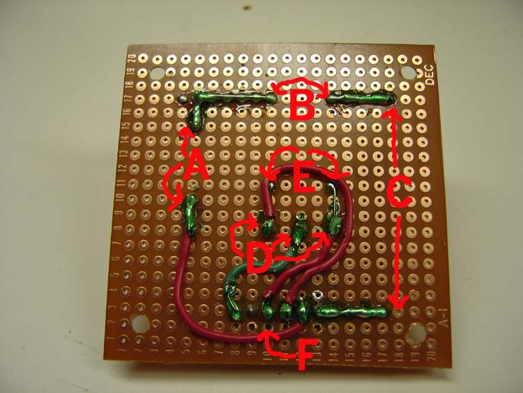
Now comes the fun! Building the Control Board:
- +20vdc from power driver flashlamp supply (Red/White Wire) onto the board through one pin of the Molex 6 pin 0.156" Header
- Through 2 amp fuse holder
- Connect to non banded side of the 1n4007 diode
- Connect banded side of 1n4007 diode to one leg of the 1 ohm 10 watt resistor
- Connect the other leg of the 1 ohm 10 watt resistor then out to the motor through one pin of the 6 pin 0.156" Header.
- Return side of motor onto board through one pin of the 6 pin 0.156" Header
- Connect to the Emitter (right leg) of TIP36 transistor.
- Take the Collector (center leg) of TIP36 transistor out to ground through one pin of the 6 pin 0.156" Header
- Take the Base (left leg) of theTIP36 transistor out to Q34 of Power Driver board through one pin of the 6 pin 0.156" Header; (I tied into the connector at J125, pin 8 in the head. See picture below.)
- Attach the 220 ohm 1/4 watt resistor from Base leg to Emitter leg of TIP36 transistor.
Note when looking at the front of the transistor the left leg is the Base, the center leg is the Collector and the right leg is the Emitter
Wiring the Cabinet
 Board is mounted on left side of game cabinet towards the front using nylon spacers and screws. Be very careful not to drill holes through side wall of cabinet! Note the location of the green ground connection in background.
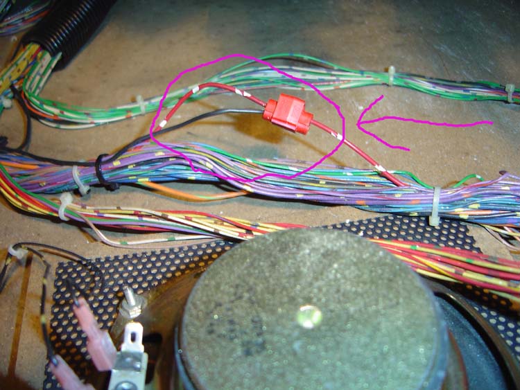 Supply +20vdc from power driver flashlamp supply (Red/White Wire) to the control board through the pin of the Molex 6 pin 0.156" header and plug that attaches to the 2 amp fuse holder on that board. Pull the Red with White wire out of the wiring loom behind the speaker (it's the larger of the three looms with all the purple wires) and connect .
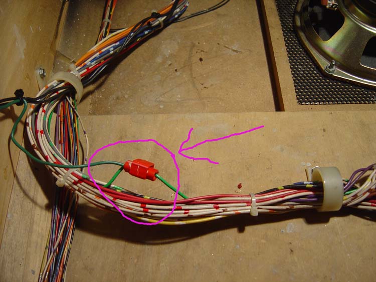 Here's a close up of the ground connection coming from the Collector of TIP36 transistor out to ground through one pin of the 6 pin 0.156" header and plug on the controller board. Pull the green wire out of the wiring loom in the bundle in front of the speaker and make the connection.
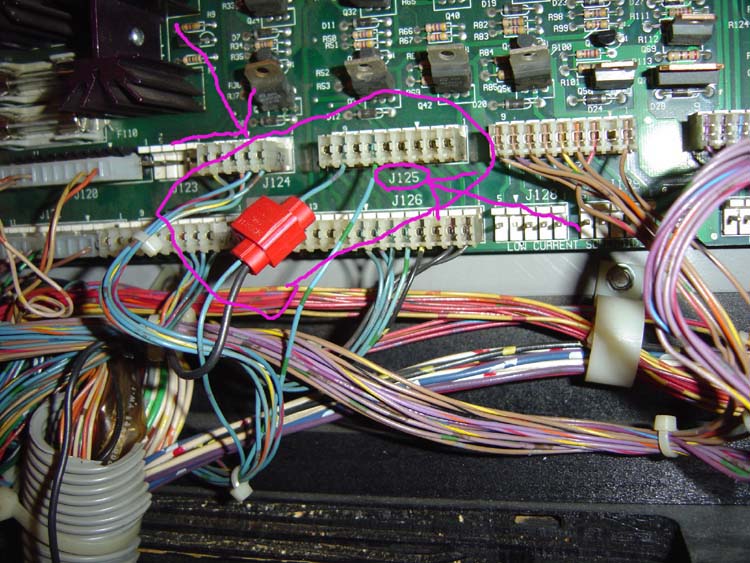 Take the Base of theTIP36 transistor out to Q34 of Power Driver board through one pin of the 6 pin 0.156" header and plug from the controller board and run it up into the head. I tied into the connector at J125, pin 8 at the bottom of the Power Driver Board in the head.
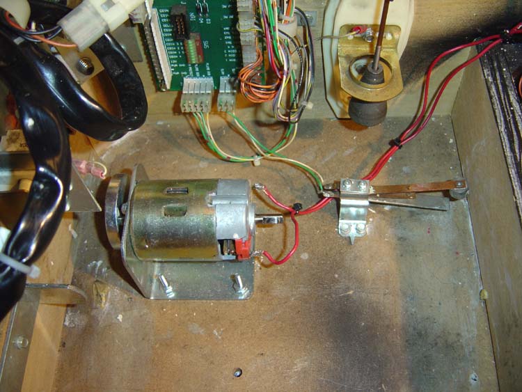 "Locate an area in the front of the cabinet for the shaker motor where it wont hit the playfield support rails when the playfield is down or the coin box. Mount using nuts and bolts through the cabinet bottom." .
That's it, now go kill some Borg!
A final note from the author and designer:
"If you follow the news group thread back to its beginning, I was asking for help in this design. I had used a 12 volt supply from the power driver board as the motor is 12 vdc. This would cause the shaker motor to run constantly if the coin door was open or if the 18vdc fuse blew open. This problem was caused by the flasher transistors closing and the 12vdc would back feed through the motor and ground through the flasher control. I then realized my mistake and supplied the motor with the same voltage source as the flashers. Thus, power to the motor is cut whenever the coin door is open."
Back to the Home Page